Table of Contents
Build Your Own Attenuator
Discussion
In my experience in professional radio, nobody uses dummy loads. We normally use attenuators. Either we connect transmission equipment to one side of an attenuator and connect measurement equipment (spectrum analysers, protocol analysers, reference receivers, etc.) to the other side; or we connect signal generators to one side and connect receivers to the other side. The attenuator simulates the path loss between transmitter and receiver.
Typically power attenuations for this kind of application will be in the range of 60dB to 120dB loss. 80dB loss changes an input of 0.5v RMS into an output of 50μV – S9 signal as received by a HF receiver.
Circuit
The inside of the attenuator is normally a simple L or Pi attenuator constructed of resistors with very little reactance (inductance or capacitance) producing 60-100dB of attenuation between the two ports. At least one port needs to be able to handle high powers.
High power RF resistors generally connect one end to ground (the heatsink) so a Pi attenuator circuit is best. Here is a Pi circuit (source – Wikimedia Commons)
For a 50Ω attenuator, R1 and R3 are slightly more than 50Ω, and R2 is many times 50Ω – such that 1/R1 + 1/(R2+R3) = 1/50
There are various online calculators that can be used, but the calculated values for an 80dB attenuation are:-
* R1, R3 = 50.01Ω
* R2 = 250kΩ
In practice, value of 50Ω are well within the tolerance of practical resistors.
R1 and R3 need to be capable of handling almost all the power required, and the R2 needs to handle a percentage of it. For my construction I used a 450W resistor for R1, a pair of 3W rated 500kΩ resistors in parallel for R2, and a pair of 1.5W rate 100Ω resistors in parallel for R3. This gives a 450W capacity from the left-hand port and a 3W capacity from the right hand port.
The 450W resistor is a special part intended as an RF resistor. Both RS and Mouser carry suitable parts. The other two are large surface-mount resistors – 1206 or bigger. Through-wire resistors can be used but not film type, as they tend to be trimmed with a spiral cut through the film, making something that is effectively an inductor at radio frequency.
For the same reason, wire-wound resistors are absolutely useless in this case, because they are inductors which also happen to have some resistance.
Remember, we need to keep the reactance low!
Parts
* R1 = 50Ω resistor, power of the left-hand port (I used 450W)
* R2 = 250kΩ resistor, about 1% of the total power (I used 2 x 3W 500kΩ in parallel)
* R3 = 50Ω resistor, power of the right-hand port (I used 2 x 1.5W 100Ω in parallel)
* Connectors and wire (I bought a pigtail that had a BNC at one end and an SMA at the other, and an N-type chassis mount with an SMA on the back)
* Metal box that can sink the heat (I bent some 50mm x 3mm aluminium strip into half a box – another piece of aluminium sheet can make a lid.)
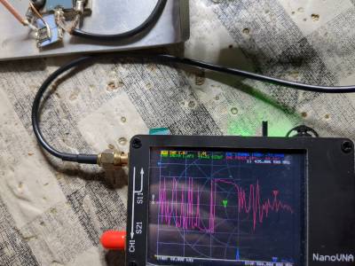
You will also need things like a soldering iron, drills, spanners and screwdrivers to fit the connectors, and some way of measuring RF impedance. I used a NanoVNA but any RF source coupled with a SWR meter should also work.
Construction
Construction should be fairly simple: each port needs a coaxial connector, and the high-power resistor(s) need to be bolted to the box with some heatsink compound and a little solder tag to connect to the resistor end. The Pi network should be assembled with as short connections as reasonably practical, as every wire at RF is an inductor and a capacitor.
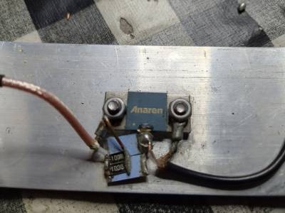
Here is my ugly soldering:-
* R1 is the large resistor labelled “Anaren”
* R2 is the pair of pale blue resistors
* R3 is the pair of black resistors numbered 100 0
The black feeder is connected to the port on the left of the diagram; the copper-coloured feeder is connected to the port on the right of the diagram. The black resistors are 1206 form factor so they're about 6.5mm and about 3mm wide.
Even though the soldering is ugly the wires are quite short which, as you will see below, gives good performance up to 500MHz or so.
Testing
Test that both the inputs produce the expected SWR measurements and impedance values (my NanoVNA said 49.something ohms and a few 100s of pF of capacitance in the 70cm band.) Also test that shorting out one port does not change the impedance values of the other by very much.
If these tests pass, you have an attenuator.

