Table of Contents
Antenna Systems
Antenna Types
The Simple Dipole
A simple dipole can be created from any piece of wire you have lying around.
A dipole will normally be a half wave length for the band you are intending to work on.
A dipole has a characteristic impedance of 73 ohms, though hams normally ignore this since it's fairly close to 50 ohms.
Dipoles are band specific.
This is the wiring of a dipole at the end of a piece of coax cable. Notice the red arrow marked C.
C is undesirable unbalancing of the dipole due to the fact that the outer skin of the braid of the coax cable is not isolated from the antenna, i.e. B and C are common. To counteract this, a balun is often used. See:
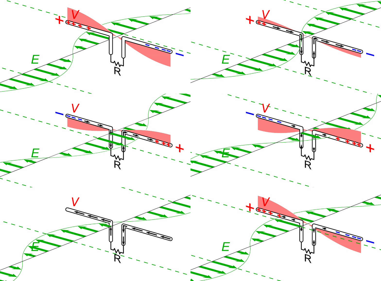
This animation shows current and voltage curves on a dipole.
Good Resources
https://www.hamradiodx.net/beginner-hf-antennas
https://www.radio4all.org/how-to-build-a-dipole-antenna/
Dud Charman's Aerial Circus
The Vertical
The Amateur Radio HF vertical antenna is a type of radio antenna designed for use in the high-frequency (HF) range of the radio spectrum. It typically consists of a vertical radiating element, often a vertical conductor or set of conductors, supported by a mast or other structure. HF vertical antennas are popular among amateur radio operators for transmitting and receiving signals on multiple HF bands. They offer an omnidirectional radiation pattern, making them suitable for general communication, and their vertical orientation helps in minimizing ground losses. Some variations may include additional features such as radials to improve efficiency and performance.
The Doublet
The Amateur Radio HF Doublet is an antenna design used by amateur radio operators for transmitting and receiving high-frequency (HF) signals. It consists of a balanced, center-fed dipole, meaning it has two equal-length arms extending in opposite directions from a central point. The doublet is often fed with a balanced feedline, such as ladder line, and requires an antenna tuner to match impedance.
Amateur radio operators favor HF doublets for their versatility across multiple HF bands. By using an antenna tuner, operators can adjust the length and configuration to resonate on various frequencies within the HF spectrum. The doublet's ability to operate on multiple bands makes it a flexible choice for HF communication, particularly in situations where a single-band antenna may be impractical.
The Loop
The Amateur Radio HF Loop is an antenna design used in amateur radio for transmitting and receiving high-frequency (HF) signals. It is characterized by a loop-shaped conductive element, and there are various types, including magnetic loops and electric loops. Magnetic loops often employ a resonant loop of wire with a variable capacitor for tuning, while electric loops may consist of a full loop which can be very large to very small or a small section of a loop with a capacitor for tuning.
HF loops are popular among amateur radio operators for several reasons. They can be compact, making them suitable for situations with limited space. Additionally, they can exhibit directional characteristics, allowing operators to focus their signal in specific directions. HF loops are often used in portable or temporary setups and can provide efficient performance when tuned properly. The tuning process is crucial to achieving resonance and optimizing performance on a specific HF frequency.
The Full Wave Loop
Definition A full wave loop is, as the words imply, a continuous loop of wire or other conductor approximately one wavelength long, usually with the two ends of the loop connected to the feedline.
The exact length for resonance depends on the diameter of the conductor and the shape of the loop, but typically it is slightly longer than a physical half wavelength at the resonant frequency. A traditional formula for the length in meters is 306 / MHz (or 1005 / MHz in feet), but, like the similar formula for a dipole, this must be considered only an approximation. Unlike dipoles, larger diameter conductors require a larger circumference for resonance. Full Wave Loop Characteristics The full wave loop forms a second basic building block of antennas, along with the the half wave dipole. In fact, the two are similar in many ways: the full wave loop can be thought of two dipoles with the ends connected together, or a folded dipole opened up into a 2-dimensional shape.
Compared to a half wave dipole, a full wave loop has a bit of broadside gain due to the separation between the two wires, though that is lessened slightly due to the shortening effect of bending the ends so they join.
The current on a full wave loop antenna is maximum at the feedpoint, and at the point of the loop opposite the feedpoint. Current is minimum at the points midway between those two. Due to the phase reversal along the wire, the currents are in phase when viewed broadside to the loop.
If we look at the radiation patterns of regular polygons in free space, fed either at a corner or in the center of one side, there is not a lot of practical difference among them:
The Mag Loop
Magnetic loop antennas
The Amateur Radio HF Magnetic Loop Antenna is a specialized design used by amateur radio operators for transmitting and receiving high-frequency (HF) signals. It features a loop of wire with a capacitor that enables tuning for specific frequencies. Magnetic loops are distinguished by their ability to generate a strong magnetic field within the loop, which contributes to their effectiveness.
Key characteristics of HF Magnetic Loop Antennas include:
- Compact Design: Magnetic loops are often more compact compared to traditional wire antennas, making them suitable for situations with limited space, such as urban environments or small backyards.
- Directional Characteristics: These antennas can exhibit directional properties, allowing operators to focus their signals in specific directions by adjusting the loop's tuning.
- Variable Capacitor: The inclusion of a variable capacitor in the loop's design enables the operator to tune the antenna to resonate at a specific frequency or within a narrow frequency range.
- Efficiency: When tuned properly, HF magnetic loops can provide efficient transmission and reception, especially on specific HF bands.
- Portability: The compact nature of magnetic loops makes them suitable for portable operations, and they are often favored by amateur radio operators engaged in field activities or contests.
While HF magnetic loops offer advantages in certain scenarios, they may also have limitations, such as lower power handling capacity compared to larger antennas. Additionally, precise tuning is crucial for optimal performance, and adjustments are often needed when changing operating frequencies.
The End Fed
The End Fed Half Wave
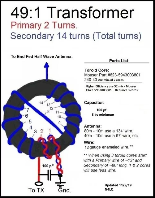
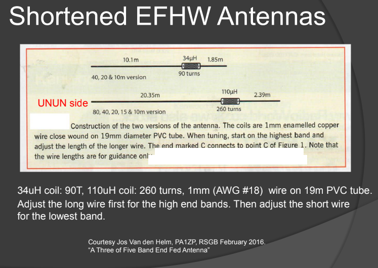
EFHW, or end-fed half wave, is generally a 49:1 or 64:1 unun with a wire cut for a specific band, often 40m or 80m (so approx. 20m or 40m of wire). When cut correctly, they can be resonant on several higher amateur bands, including the even harmonics.
These generally benefit from a counterpoise wire, and when correctly adjusted, do NOT need a tuner.
This behaves like a dipole on the band it is cut for, but the pattern less like a dipole and compromised more the higher bands it is operated on.
The End Fed Long Wire / Random Wire
EFLW, or end-fed long wire, is generally a 9:1 unun with a “random” wire. In reality, the “random” wire needs to be cut to avoid specific lengths in order to be matchable on the ham bands.
The idea with an EFLW is for the transformer to bring the high impedance of the end of a piece of wire down in to the matching range of a typical tuner in the ham bands, i.e. a tuner is required for this antenna.
Resources:
Both the EFHW and EFLW can be deployed in creative ways, e.g. slopers, wound around poles, inverted L, fully horizontal, but might need some adjustment to compensate for that (and the surroundings).


