This is an old revision of the document!
Antenna calculators
Moxon 2m Final lengths of copper 15mm pipe were:
1 x 707mm
2 x 352mm
2 x 132mm
2 x 74mm
(Plus four 15mm corners)
Tuning Gap 45mm
Feedpoint gap 2mm
Coax connected via 4mm brass screws, via a tapped hole in the copper and wood underneath, which makes the connection on the front side solid Note, it wasn’t an exact science and it isn’t perfect, actual 1.0SWR is at 142mhz not 144.5 — but since it’s at 1.1 at 144.5 I am fine with it Wooden dowel rod, cut to the exact length that it fits to leave the 45mm gap All parts shrunk including long part of radiator
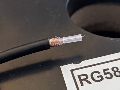
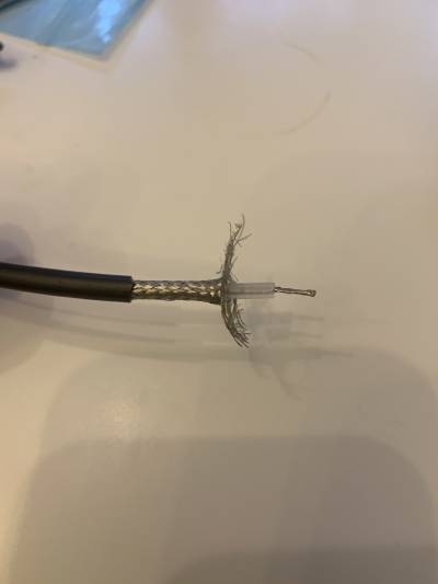
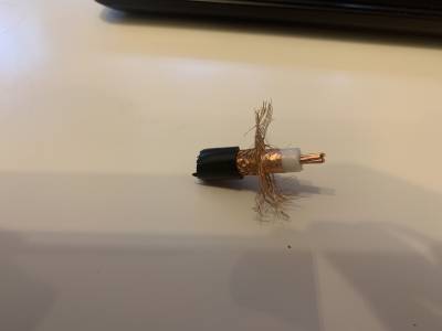
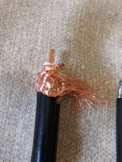
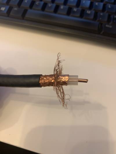
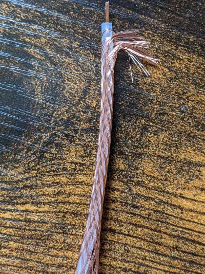
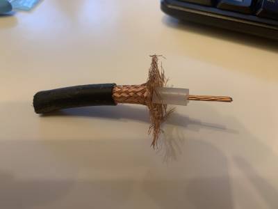
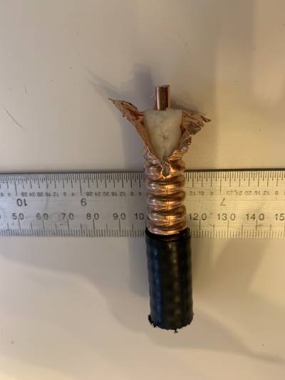
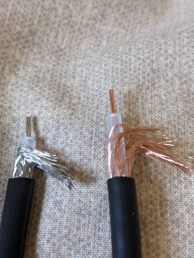
RG58 coax pictures
Left is rg58 milspec from Nevada Radio I believe. Right is cheap stuff from Amazon (£10 for 30m). Is be interested to hear what people think of the cheap stuff
nanoVNA
On a different tack I came across this on qrz and thought it would be useful info to anyone using a VNA. First the data from measuring a 50 Ohm dummy load as a reference point..
- LogMag ——————————————— 10dB / -30.6 dB
- Phase ———————————————— 90degrees / -1.786 degrees
- Delay ———————————————— 1000p / signal varying between -1.3ns and 0.966ps
- Smith ———————————————— 1.0FS 47.1Ohms 700nF
- SWR ————————————————- presents 1.06 the ratio part of vswr.
- Polar ————————————————- 1.0 FS -0.029 -0.029j (again means nothing to me)
- Linear ———————————————— 125m / 0.029
- Real ————————————————– 250m / 0.029
- Imag ————————————————- 250m / 0.000j
- Resistance —————————————– 100 / 47.1 ohms
- Reactance —————————————— X 100 / -64.7 mOhms
Information explained
Many of these options show the same information in slightly different ways. When you are making One port measurements. (Using just one connector of the VNA), Some of the parameters are not very useful. The first number before the slash/ is the scale so the first one is 10dB per vertical division.
1. LogMag means that you are taking a return loss measurement. You only have the magnitude and it will report the value in dB scale. This is not a vector measurement by itself. Return loss is really just another way to look at VSWR. The reflected signal energy is lower if the match to the transmission line is good. If you are interested you can look up conversion between return loss and VSWR. It really is just the same thing with different units.
2. Phase. If you combine this with the Log mag measurement then you will have a vector measurement. You will know how much the reflected energy is reduced from the LogMag and you will know what angle the reflected signal is relative to the forward signal. You can convert this vector measurement magnitude and phase to the other ones if you wish by math transformations.
3. Delay. This is normally used for a two port measurement, but it really is another way to look at the delay if using a one port measurement. Not really meaningful and prone to errors for one port measurements.
4. Smith Chart. Just a visual way to look at complex impedance measurement. Same info as from LogMag and Phase. If you like it use it. If not use one of the others. 5. SWR. I think you get this one. 6. Polar. Just another way to visualize the magnitude and phase. 7. Linear. This is just the normalized magnitude of the reflected signal but in linear units instead of log (dB) 8. Real. This is the normalized resistive part of the impedance measurement. 9. Imag. This is the normalized imaginary or reactive part of the impedance measurement. 10. Resistance. This is probably the thing that is easiest to understand. This is the un-normalized real resistance of the impedance.
TOM M0LTE Packet over HF
HF Packet, based on a working Windows digimodes setup.
1. download http://uz7.ho.ua/modem_beta/soundmodem114.zip
2. install. Start. Allow firewall exceptions if any pop up. (might not be necessary)
3. settings → devices → audio input/output as per WSJT-X
4. settings → devices → select PTT port (it uses CTS/RTS PTT, not CAT)
5. main window, select AFSK AX.25 300bd
6. download http://uz7.ho.ua/apps/easyterm49.zip
7. install, run
8. settings → station setup → Terminal Callsign: your call
9. Follow any prompts to restart EasyTerm
10. Start EasyTerm, click Connect, set CallFrom to your call, CallTo your QSO partner. Click Connect. Radio will key up.
ugh, can't find any quick instructions for soundmodem packet on Linux to point you at right now. Boils down to: install a soundcard TNC, e.g. Dire Wolf, enable its KISS interface, and connect a KISS terminal to it, e.g. https://www.cantab.net/users/john.wiseman/Documents/QtTermTCP.html
FreeDV setup
- Take a setup that successfully runs FT8
- Close WSJT-X, download and install FreeDV https://freedv.org/
- Plug in additional audio interface, the one your plan to speak and listen through, if needed
- In FreeDV, choose the two audio interfaces- the one going to/from your radio and the one going to/from your headset
- Also in FreeDV, set up your PTT method (same as in WSJT-X)
- Operate there’s a PTT button in the UI, that’s how you switch between transmit / receive.
- There are a few submodes- the high numbered sub modes refer to the bandwidth taken and therefore the quality. Less resilience with wider sub modes of course.
Older rigs for FT8
IC211/251/271/275/260/290, FT480, TS700/711, TR751, TM251, FT221/225 They will do it, but the older ones use relays which wouldn’t be too good. I think the more mobile type radios are more likely to be PIN diode based. I don’t remember my TS711 making much noise in changeover, but it is 30 years ago.

