
Table of Contents
2/70 Direct-Fed Satellite Yagi
Introduction
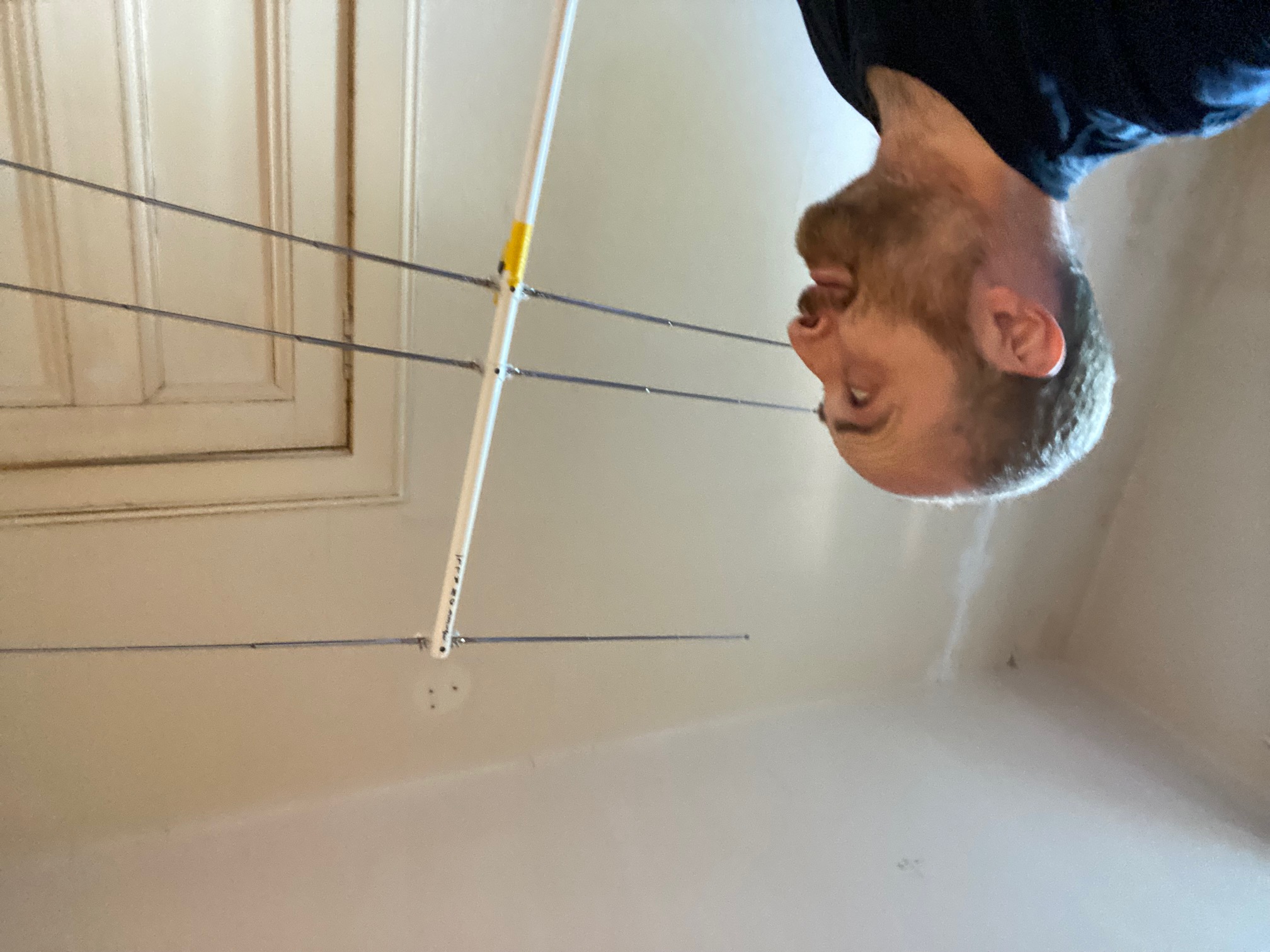 Based off a design by Adam Kimmerly K6ARK this direct-fed 50 Ohm Yagi is a stupidly simple build. It’ll get you up to satellites, it’ll work well on the ground, AND it’s adjustable and may work well across other VHF and UHF bands (at the very least on receive). SWR will be 1-2:1 on both bands depending on your tuning accuracy. The rotating elements also allow for storage without disassembly. There's a driven element, a parasitic element to bring 70cm into line, and then a director - no reflector on this antenna.
In terms of performance, this isn't an Arrow. You can expect to start hearing the satellite when it reaches around 40-45 deg elevation. This may depend on whether the downlink is UHF or VHF - but with UHF I definitely notice it taking a while for this antenna to see some signals. On VHF you'll get a bit more range I think.
Parts List
- 1m section of 20mm rigid PVC conduit
- 3 x 20mm conduit spacer bars
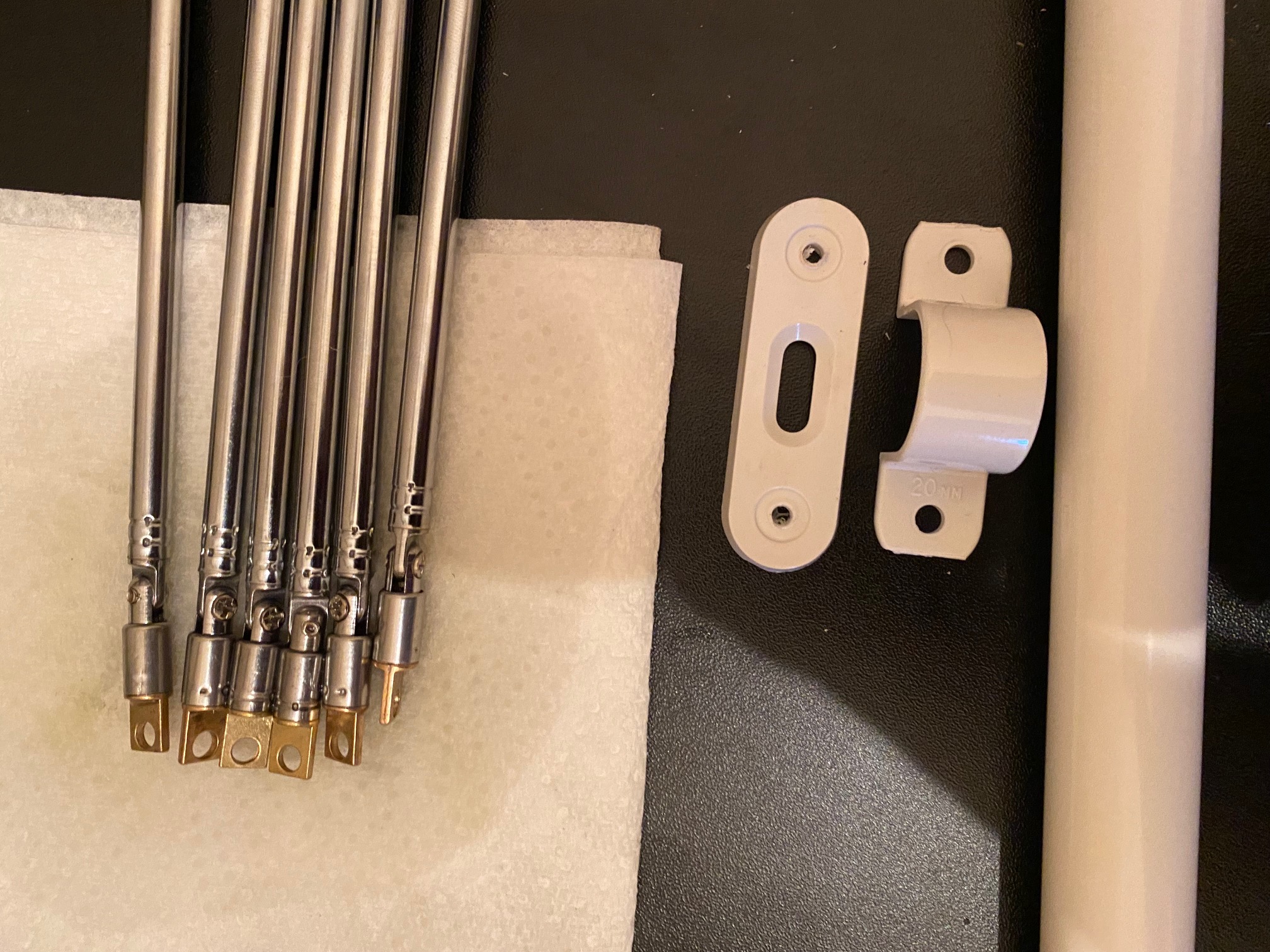
- 6 x telescopic elements - These must extend to at least 1/4 wavelength on the 2m band. They can also be rotateable if you wish for more flexibility or change to using threaded rods
- Some odd bits of wire to join two sets of elements together
- 3 x screws for clip/conduit fixing
- 6 x M3 screws, at least 15mm long
- 6 x M3 wingnuts
- 6 x M3 nuts for spacing
- Length of RG58 with whatever plug, around 1-2m long
- Clip-on ferrite
- Some electrical tape
- Glue gun if you like to go overboard like me
- A drill of some kind
- Something to make marks with (sharpie?)
Dimensions
People often give positions from the bottom element when discussing Yagi builds, but working with a handheld pole means I like to start from the top element, right at the end of the pole, as I’m trying to get things as far from my body as possible. I have converted Adam’s dimensions from bottom-up to top-down here.
Element 1 (Second Director)
- From top: 0 inches/0 cm
- Extend each arm: 18.36 in/46.63 cm
Element 2 (First Director)
- From top: 9.82 inches/24.94 cm
- Extend each arm: 19.05 in/48.38 cm
Element 3 (Driven)
- From top: 13.26 inches/33.68 cm
- Extend each arm: 20.17 in/51.23 cm
Remember when extending the elements to measure to the centre of the boom, not the end of the element. We’ll join the two sides in the middle with some wire later. This also counts for the bottom element as the coax shield and inner from each element will run roughly to the centre of the boom too.
Build Process
 Firstly, I prepped the boom. I cut my length to 1m, which puts my body sufficiently far enough away from the elements while still being comfortable-ish to hold. After that I marked some positions for elements from the dimensions given by Adam (after converting them to metric… grr…).
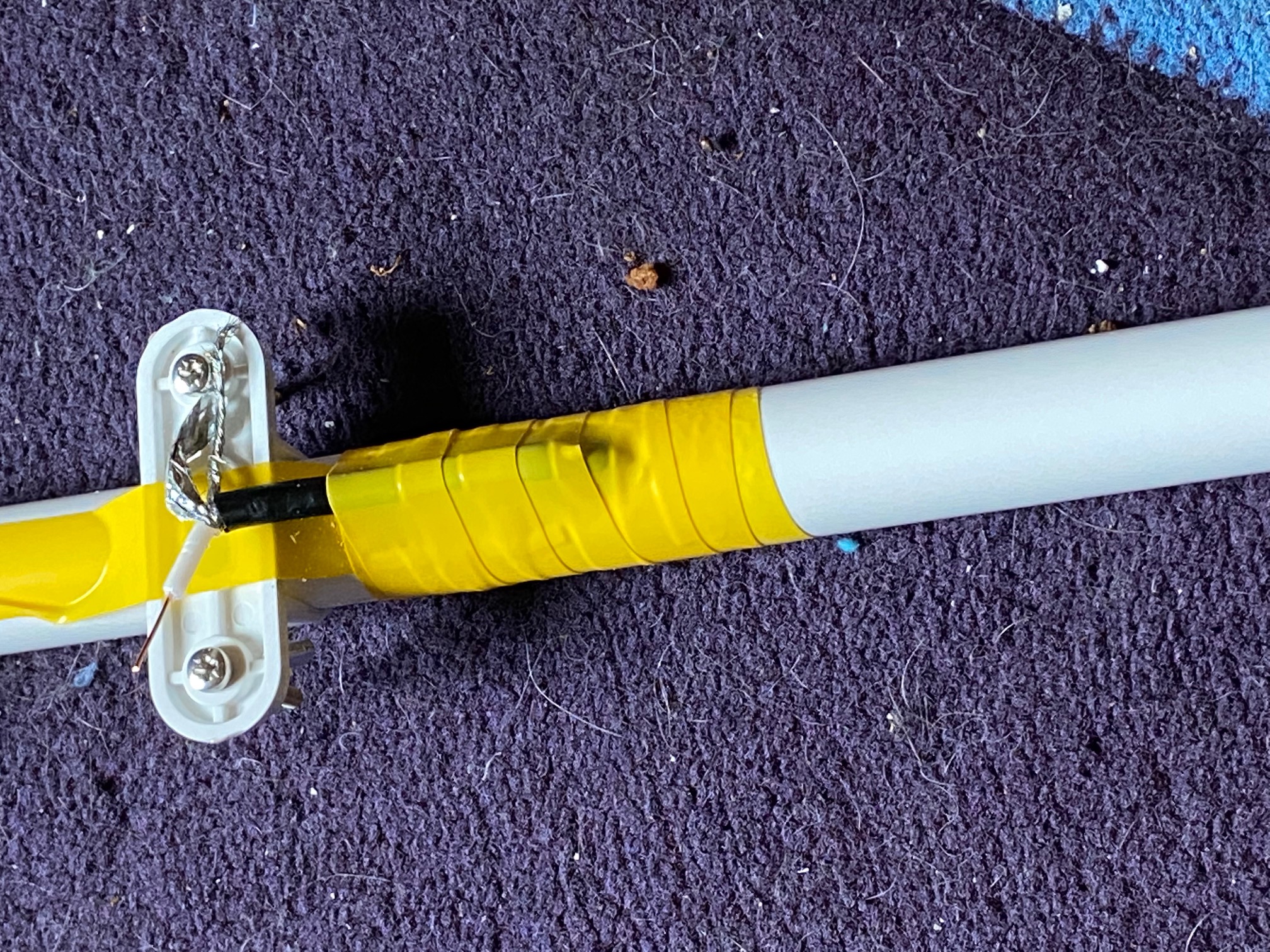
A hole was then drilled below the feedpoint and shaped to make the wire come out at a shallower angle, leaving space for a small clip-on ferrite between the feedpoint and the hole. Feed the RG58 up the bottom of the pole and out of the drilled hole. And then put the boom to one side for now. Time to make the elements.
 The antenna elements themselves were mounted on the pipe spacer bars with some long M3 screws to fit the antenna elements. The key is to insert the screws the other way up from how they are meant to be used (screwhead down). Luckily the screw holes in the spacers were juuuust about M3 size. Nothing some extra force didn’t solve.
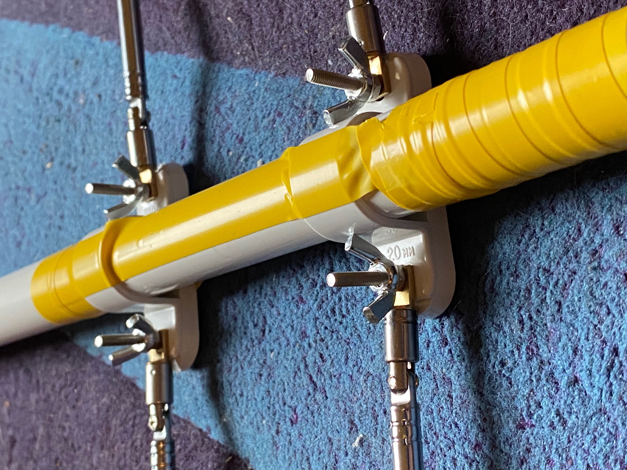
The bottom of the top two spacer bars on the boom have small lengths of solid core wire joining the two sides, wound around the screw threads tightly before screwing the screws down as far as I could. Check the continuity at this point! The two sides have to be joined together to make a continuous half-wave radiator. The bottom, driven elements have to remain separated, so just wrap the coax centre and shield - one around each thread - and screw those tightly too.
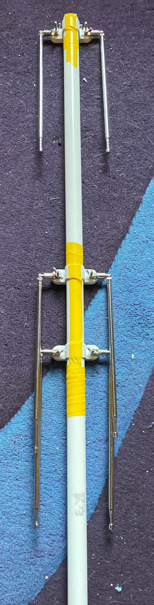
![]() I did have to file the bottom part of the spacer bar for the fatter base of the antenna elements to sit in, as well as cutting some of the top clip part. I also added an M3 nut to raise where the upper wingnuts sat. The wings themselves touch the pipe clip near the bottom of the required screwing range and it needed a lot of force to force them past. Could file the wings down, or the plastic clip a bit to sort that.
I did have to file the bottom part of the spacer bar for the fatter base of the antenna elements to sit in, as well as cutting some of the top clip part. I also added an M3 nut to raise where the upper wingnuts sat. The wings themselves touch the pipe clip near the bottom of the required screwing range and it needed a lot of force to force them past. Could file the wings down, or the plastic clip a bit to sort that.
Initially I used some tape to hold the spacer bars in place while I tuned the antenna on a VNA. I used the dimensions Adam gave as a starting point and retracted the telescopic lengths until I had a decent tune on both 70cm and 2m. I then slid the spacer bars a tiny bit back and forth and checked the tune. After dialling it in well I drilled a hole in the middle of each top clip and used some self-tapping screws to firmly secure the bars to the pole section.
And that is basically it. Keep the M3 bolts, nuts, and wingnuts tightened (this will annoy you, they are joined at only one place so things will rotate when you don't want them to or when travelling etc - is there some sort of locking nut you can use to stop this?) and make sure you don't bend any of the telescopic elements. The more you do that the more out-of-plane they'll become. For the best efficiency and radiation pattern your Yagi elements all need to be in the same plane.
The elements will, of course, bend at the right-angled join, meaning that you can store the antenna stowed, attach it to a rucksack, etc. Or you can fully disassemble and reassemble each time. Bring a spanner! And maybe a small screwdriver.
Improvements
There’s loads of ways you can improve this design. A foam grip or pistol grip would be good for the wrist - these antennas do get a little heavy and cumbersome after a while.
I’ve also considered adding a reflector behind the driven elements. There’s room for it, and it may improve the UHF downlink receive which is the only downside of this antenna (hence it only really working to 40ish degrees). I will run the model for this in MMANA-GAL and see how it helps. It may ruin the 70 cm match though.
I think the original design with arrow shafts (used on the, er, Arrow too) are a better idea for better rigidity and keeping everything aligned right. But I don’t really have much in the way of tools or skills, so drilling holes for threads and inserts scares me. But seriously, if you are okay doing that kind of work then definitely do it - it’ll be much better than my build.
A split boom somehow would also be good, just to keep the size down. How to attach the two halves together is something I’d need to think about.