
Table of Contents
CM108 Sound Interface (SMD edition)
The CM108 is a USB sound interface chip that has become popular among radio amateurs due to it's low price (~£3.50), ease of modifications, and the presence of GPIO pins for triggering things like PTT or detecting squelch opening.
There are now many different guides out there to modify them, but I recently came up with a design optimised for Dire Wolf and simplicity which I've documented below
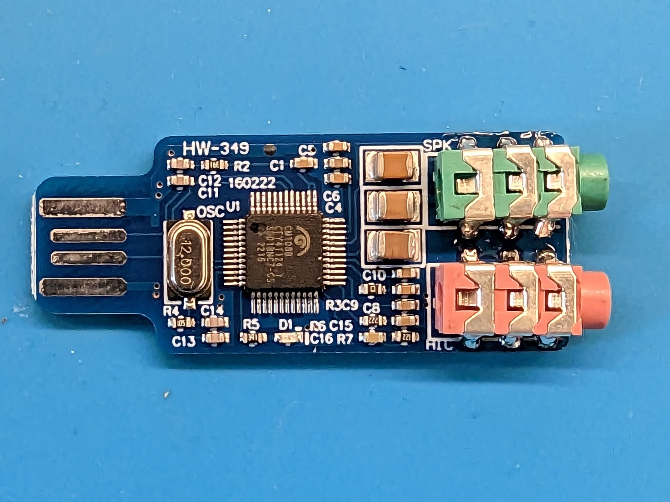
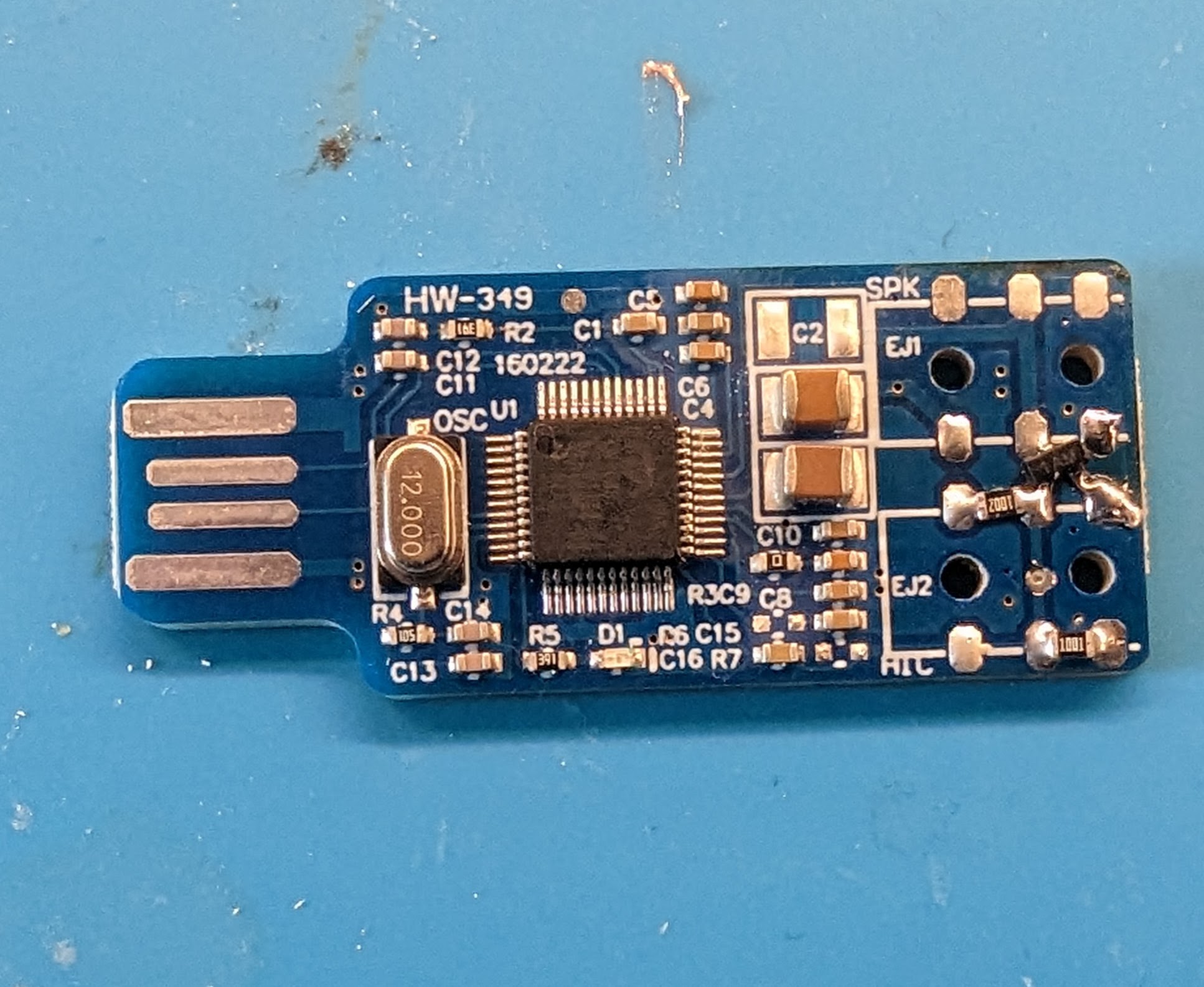
Here's what the unmodified sound interface looks like:
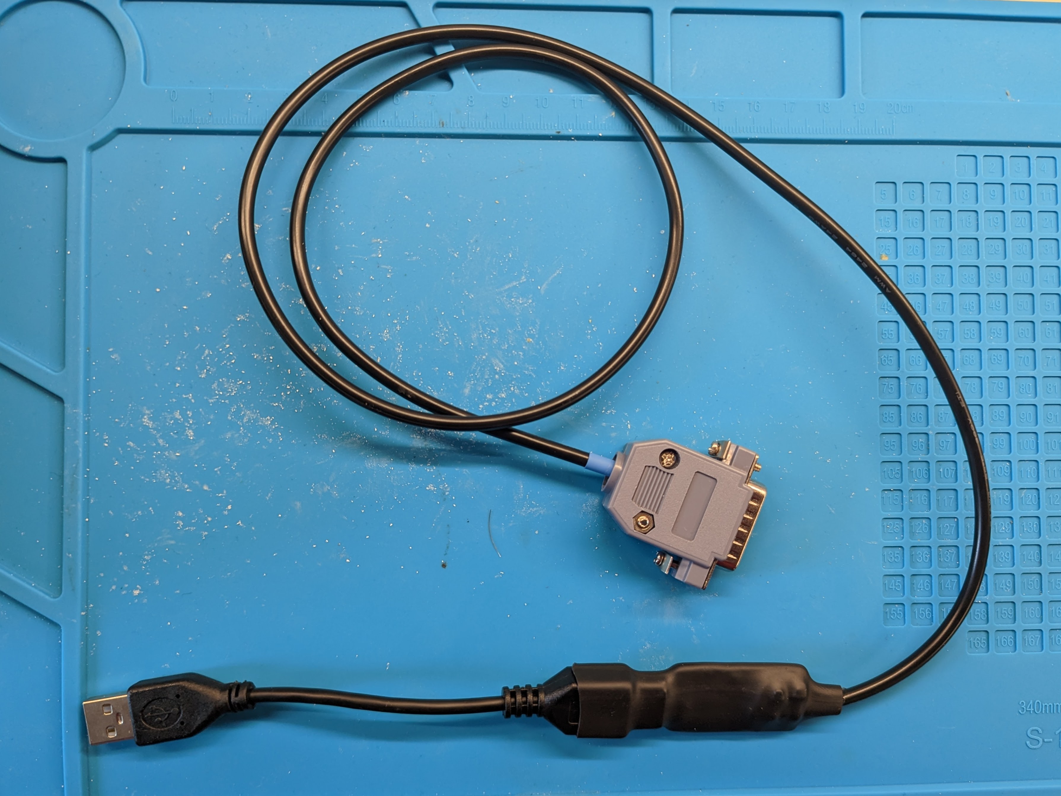
This is the completed unit with an optional USB extension cable:
Notes
- This project involves modifications and fine soldering. Getting something wrong runs the risk of damaging your radio, so be careful, check for solder bridges, and use a multi meter where you can to check and confirm things are working before plugging into your radio.
- This design assumes the PTT on your radio is active low. In theory you could swap it in software but this runs the risk of leaving your radio keyed if the software closes. Ideally if your radio is active high you'd make changes to the transistor arrangement.
- The CoS detection isn't connected in this example. It will not work with AllStar Asterisk etc, but will work with Dire Wolf for APRS and Packet
- Concerns have been raised about the longevity of the PCB track USB connector. To increase the longevity you could use a short USB extension. This also reduces the risk of damaging the sound interface when its plugged into a computer, and allows attaching a ferrite to the cable.
- I've only made minor changes to a mishmash of existing designs. Thanks to WB6NIL (SK), W9SH, M0NFI, G7RPG, G5REV and many others for coming up with various CM108 mods.
You will need
- 1x CM108 USB Sound Interface
- 1x 10k 805 SMD resistor
- 1x 1k 805 SMD resistor
- 1x 2N3904 SMD transistor in SOT-23 package
- 0.05 mm² / 30AWG Kynar Wire
- 1.8mm thick cable ties
- 4 core cable of some flavour
- A connector for your radio
- A short USB extension cable (optional)
- 4:1 Adhesive Heat Shrink. Pre-Shrink: 19mm Post-Shrink: 4.5mm
- Soldering Iron, Solder, associated tools
- Drill + 2mm drill bit
- Hot Air Station (Optional)
- Multimeter (Optional)
Modifications
Remove components
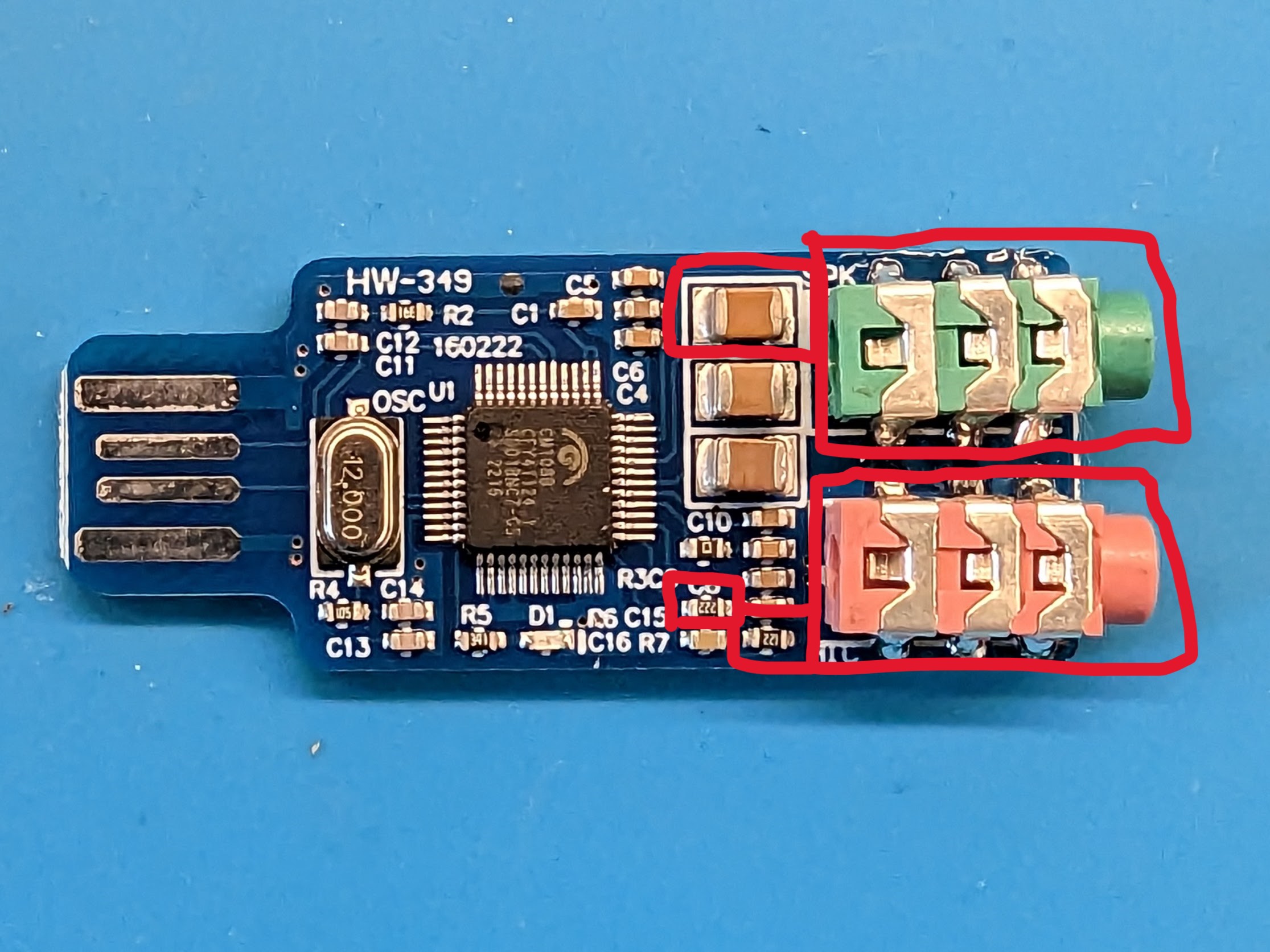
First of all you will need to remove the 3.5mm jacks and the unused components highlighted in the image below. You may find it easier to use a hot air station.
The large capacitor is removed to free up a pad for the PTT line. The two smaller resistors are removed to disconnect the DC biasing designed to power a microphone.
Drilling / Cutting Tracks
Next we need to cut a couple of tracks to free up the pads for modifications. The locations of the cut tracks are shown in the image below. You will also need to enlarge the 4 holes in the PCB to 2mm to allow the cable ties to pass through.
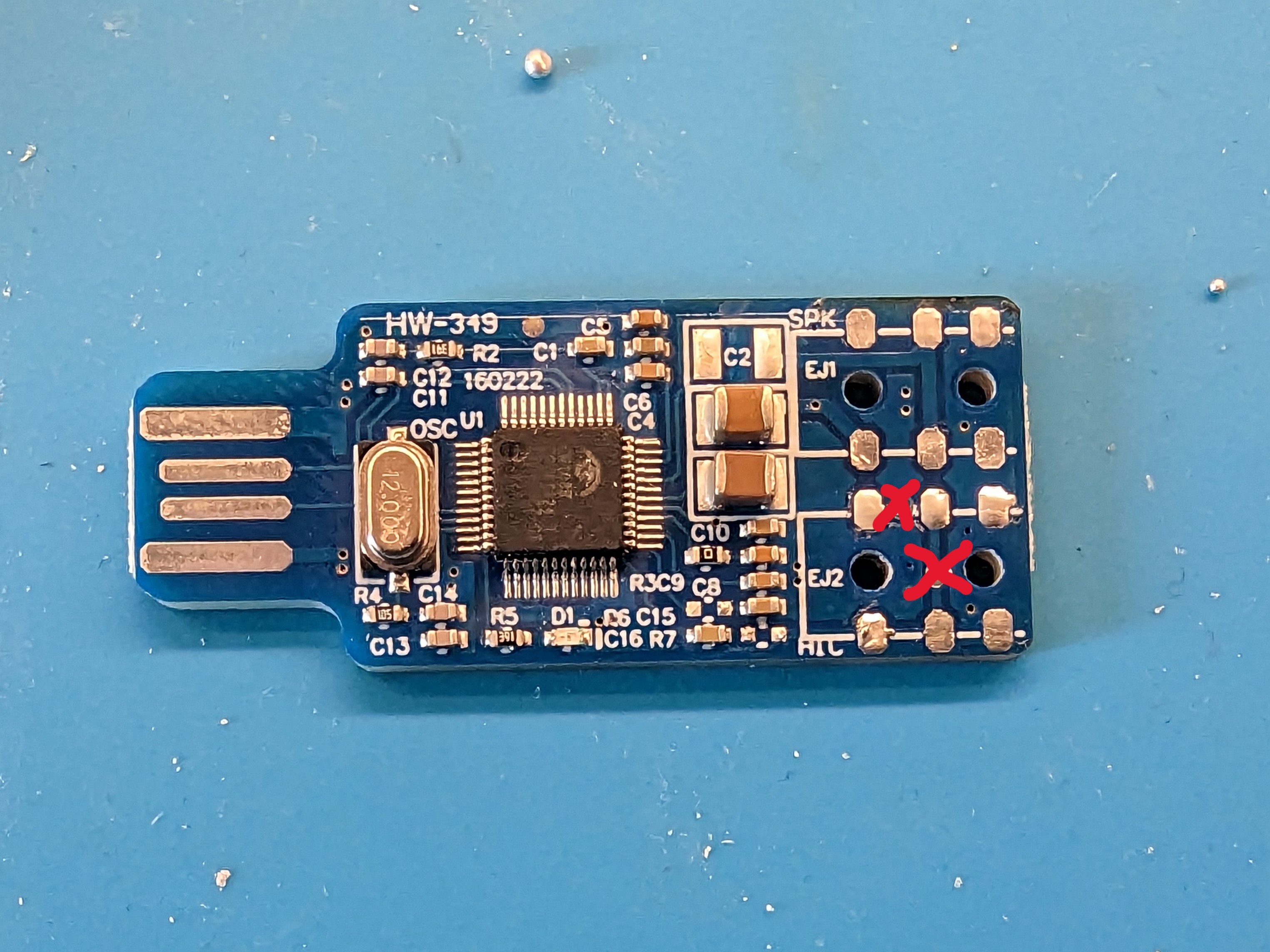
Once finished, check for continuity between the pads where tracks have been cut, to ensure they're properly isolated.
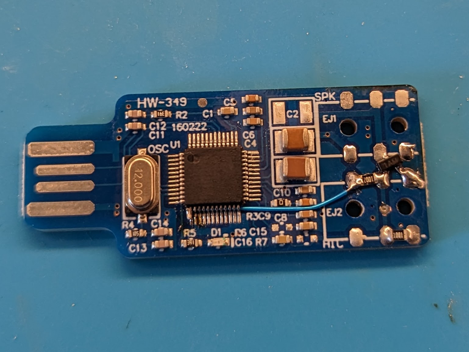
Soldering components
Next is to solder on the SMD components. The transistor is a little fiddly to get touching all 3 pads. I had to add a small bit of stripped wire to extend one of the legs.
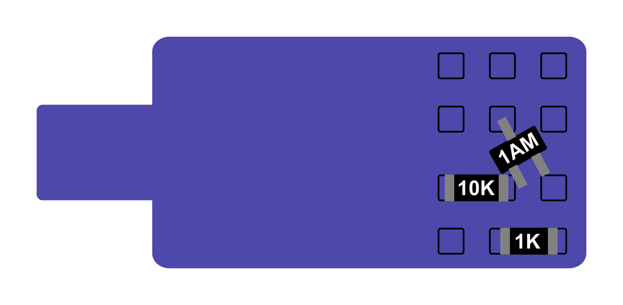
Add the PTT connection to the GPIO
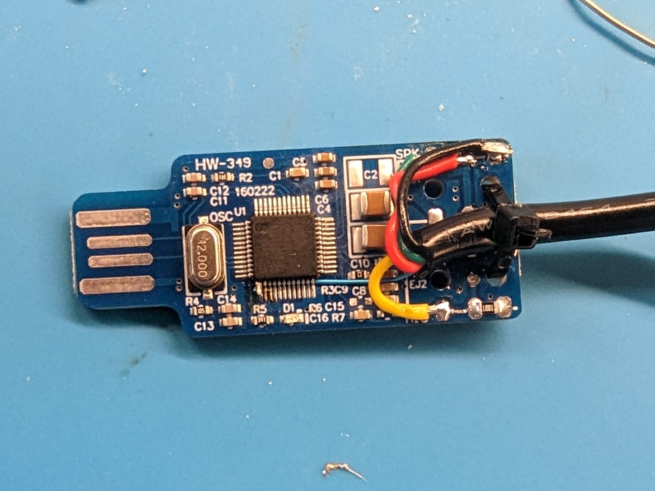
Next you have to carefully solder a wire between the PTT GPIO and the 10k resistor. I've found the simplest way is to take some 0.05 mm² / 30AWG Kynar Wire, strip a tiny amount of the insulation and then bend it slightly. Then slide the wire under the legs of the chip to keep it steady, and solder it to the pin of the chip.
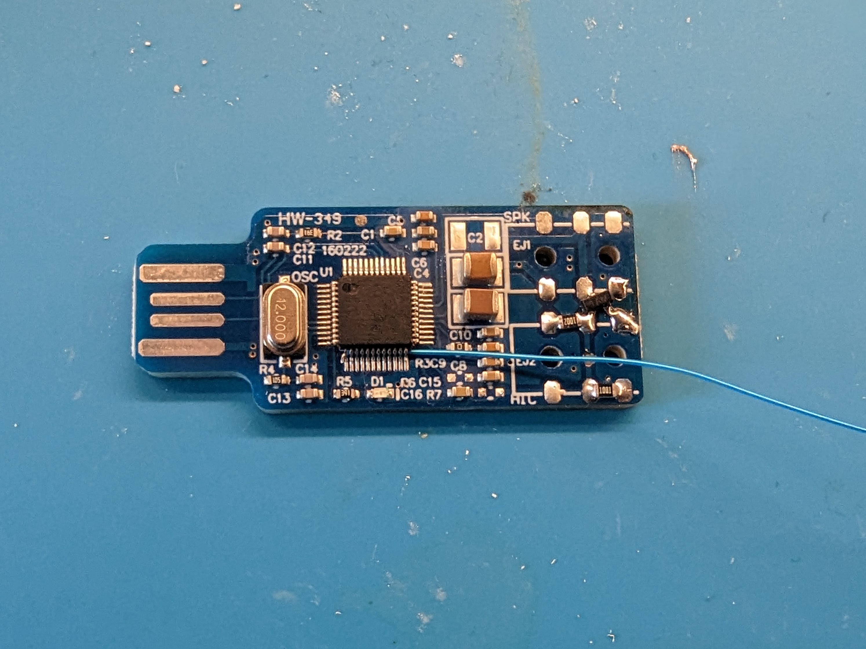
Once soldered to the chip, trim and strip the other end as required and solder to the 10k resistor:
Wiring
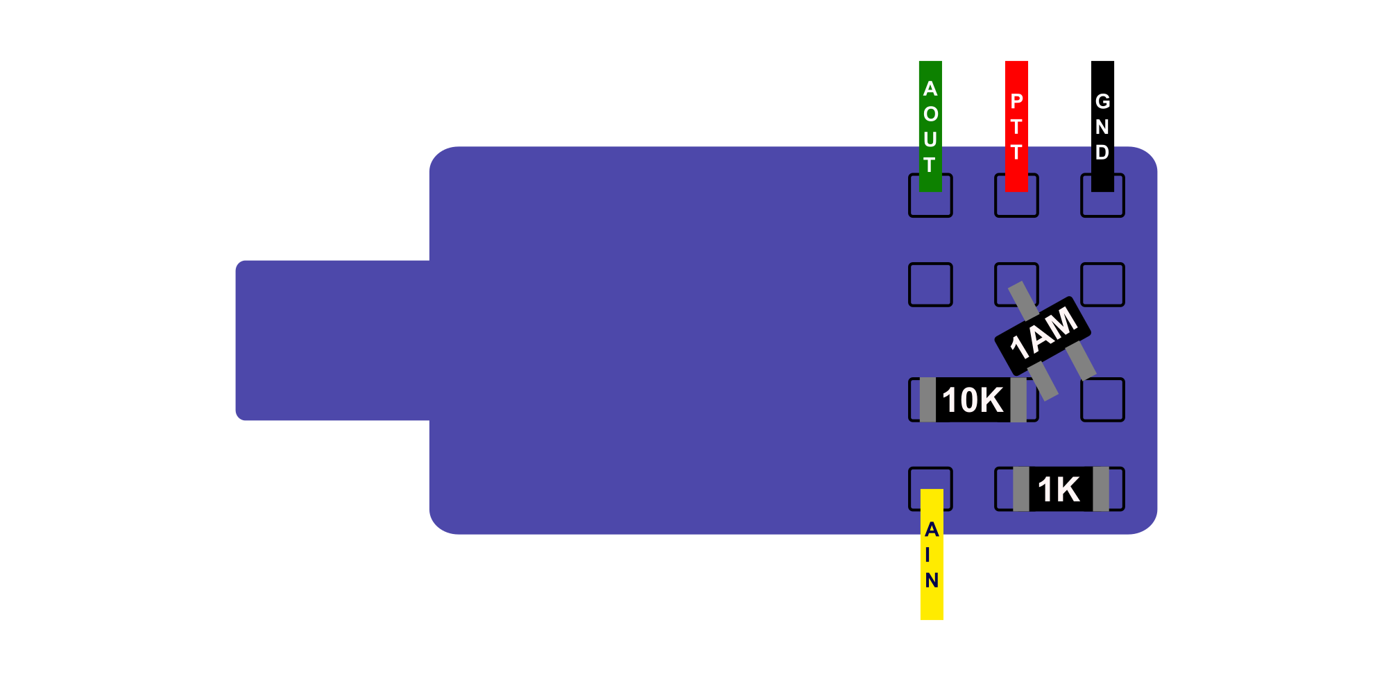
Next is to add the wiring to connect to your radio. Use the following diagram as a guide. AOUT is Audio Out from the Sound Interface, i.e what the radio should transmit. AIN is Audio into the Sound Interface, i.e what the radio is receiving:
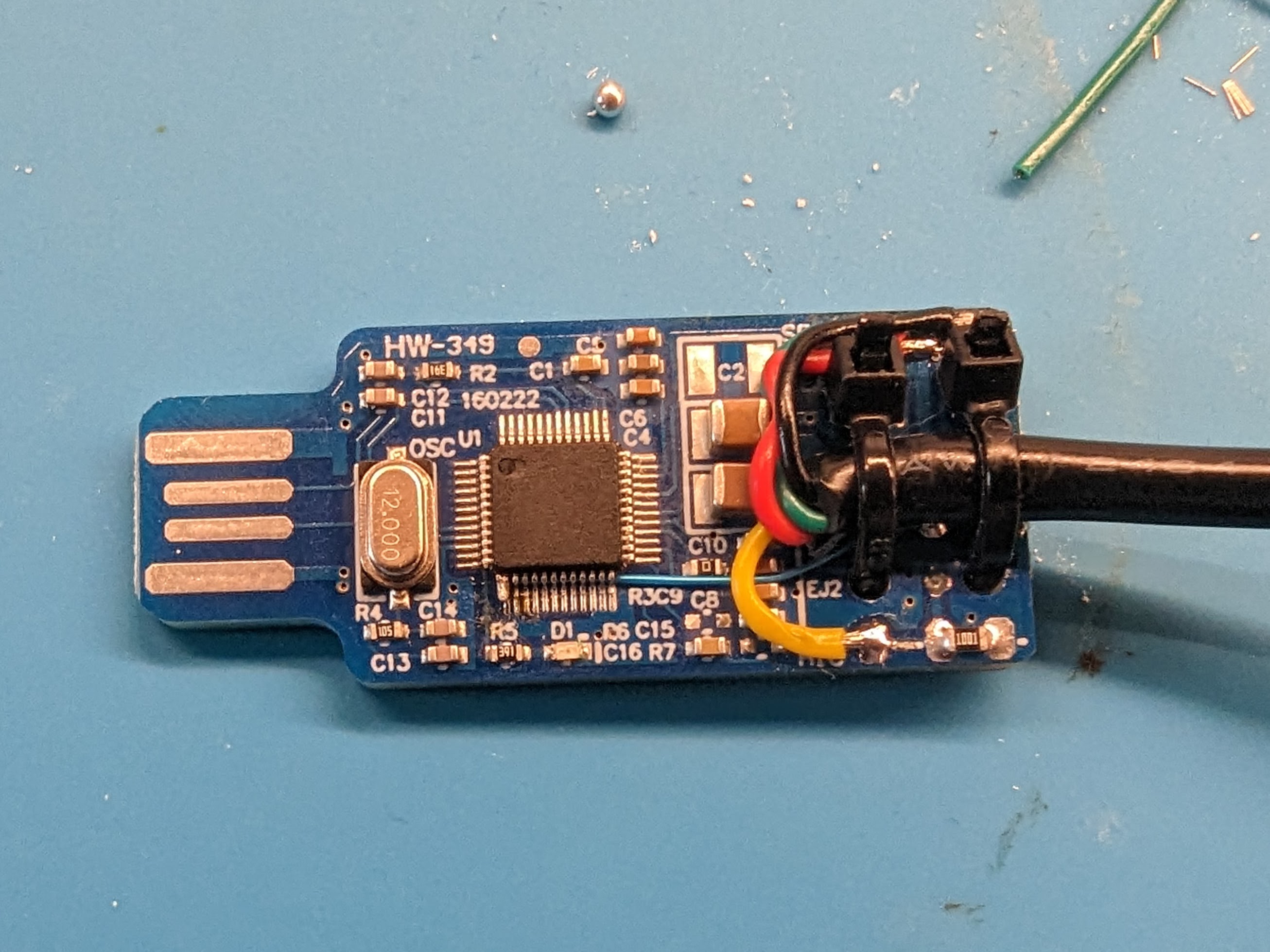
Remember to loop the individual wires such that you can later secure the main cable with cable ties. To make life easier I used a temporary cable tie to hold the cable in place, carefully tightened so it didn't get in the way of the pads.
Once soldered, remove the temporary cable tie and add two new ones to act as strain relief. This time tightening them down to keep the overall profile of the sound interface as small as possible:
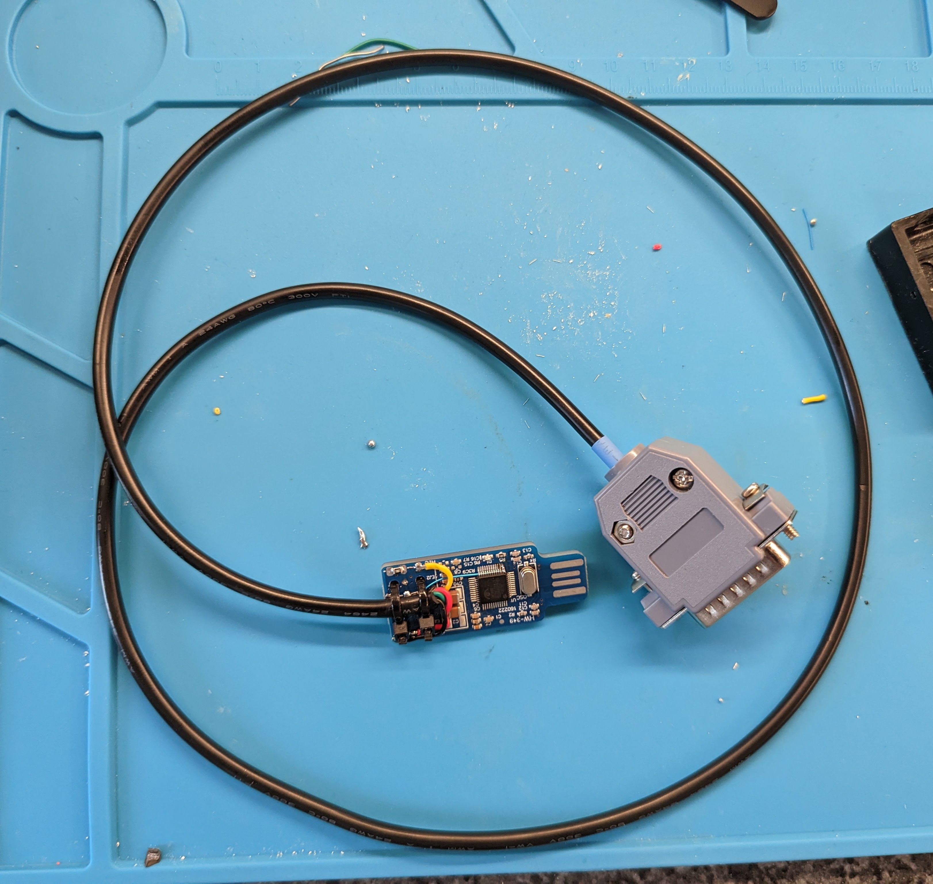
The radio end will vary according to which radio you're interfacing with, so check the documentation or wiki pages for your radio. My almost completed cable for the Tait TM8100 series looks like this:
At this stage, your cable is ready to test. Once it's confirmed working the final step is to cover the USB fob in heat shrink to avoid any shorts.