
Table of Contents
Simoco SRM9000
These radios have become popular with Radio Amateurs due the availability of a 66-88MHz version, making them ideal for use on the 4 metre band. They have come to our attention due to the reasonable availability/price of UHF models (~£55 on eBay) vs other radios such as Tait or Motorola which are hard to come by and often expensive.
One useful feature is stepped power outputs (1, 2, 2.5, 4, 5 etc) which might be useful for complying with ERP limitations without having to adjust factory calibration settings.
Note: Despite considerable testing by Matthew 2E0SIP and reverse engineering and modifications from Denis G4KWT, the rev9 version of this radio is unreliable at 9600 baud. 1200 baud works fine, and 2400 baud performance looked okay but hasn't been thoroughly tested
Models
A sticker on the bottom of the radio has a code printed on it to indicate frequencies. Watch out for models that don't cover amateur bands!
| Version | Frequencies (MHz) |
| E0 | 66-88 |
| AC | 136-174 |
| TK | 400-450 |
| TU | 400-480 |
| UW | 440-500 |
Images
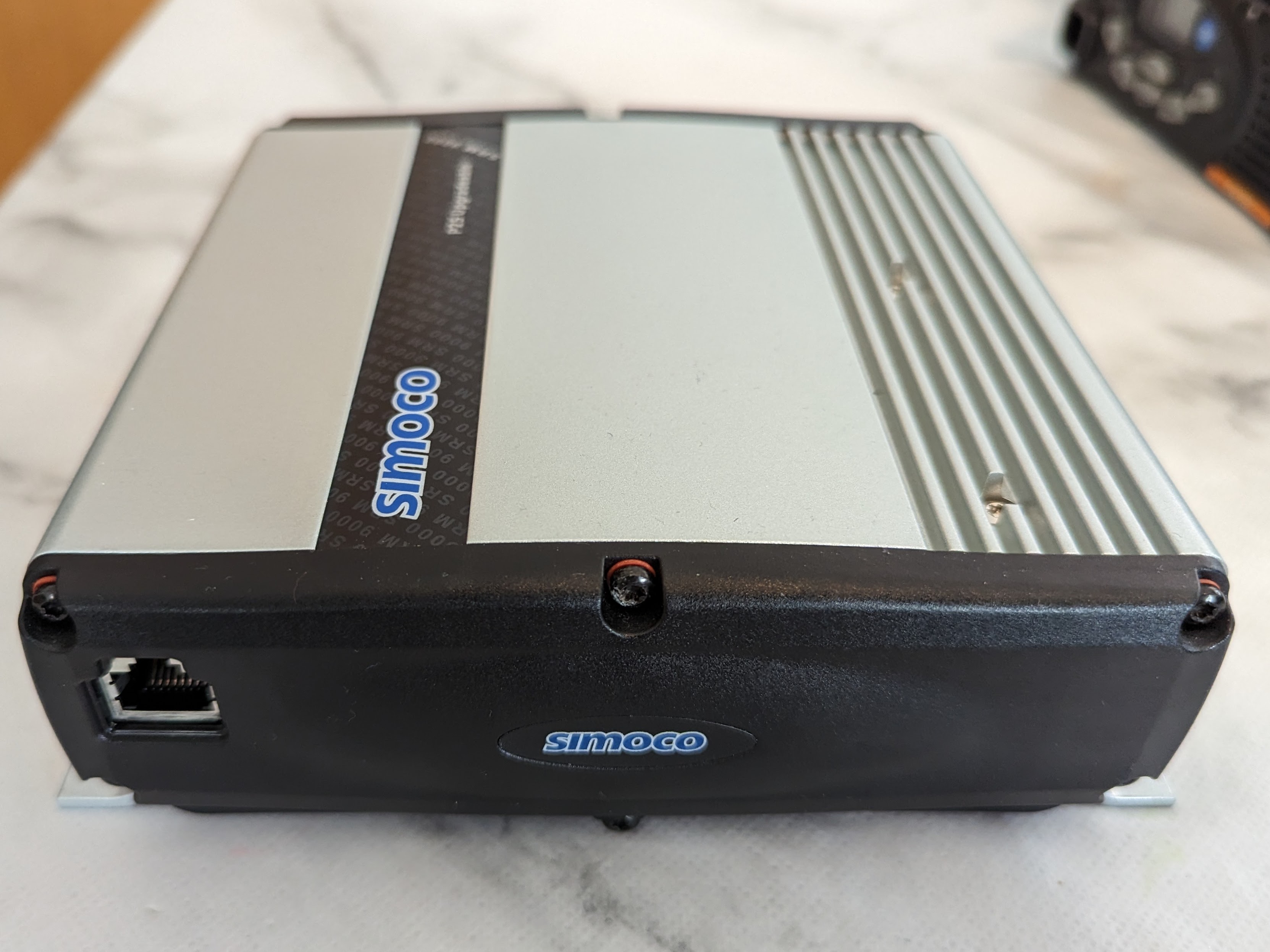
Front of the radio showing the RJ45 Mic / Control Head connector:
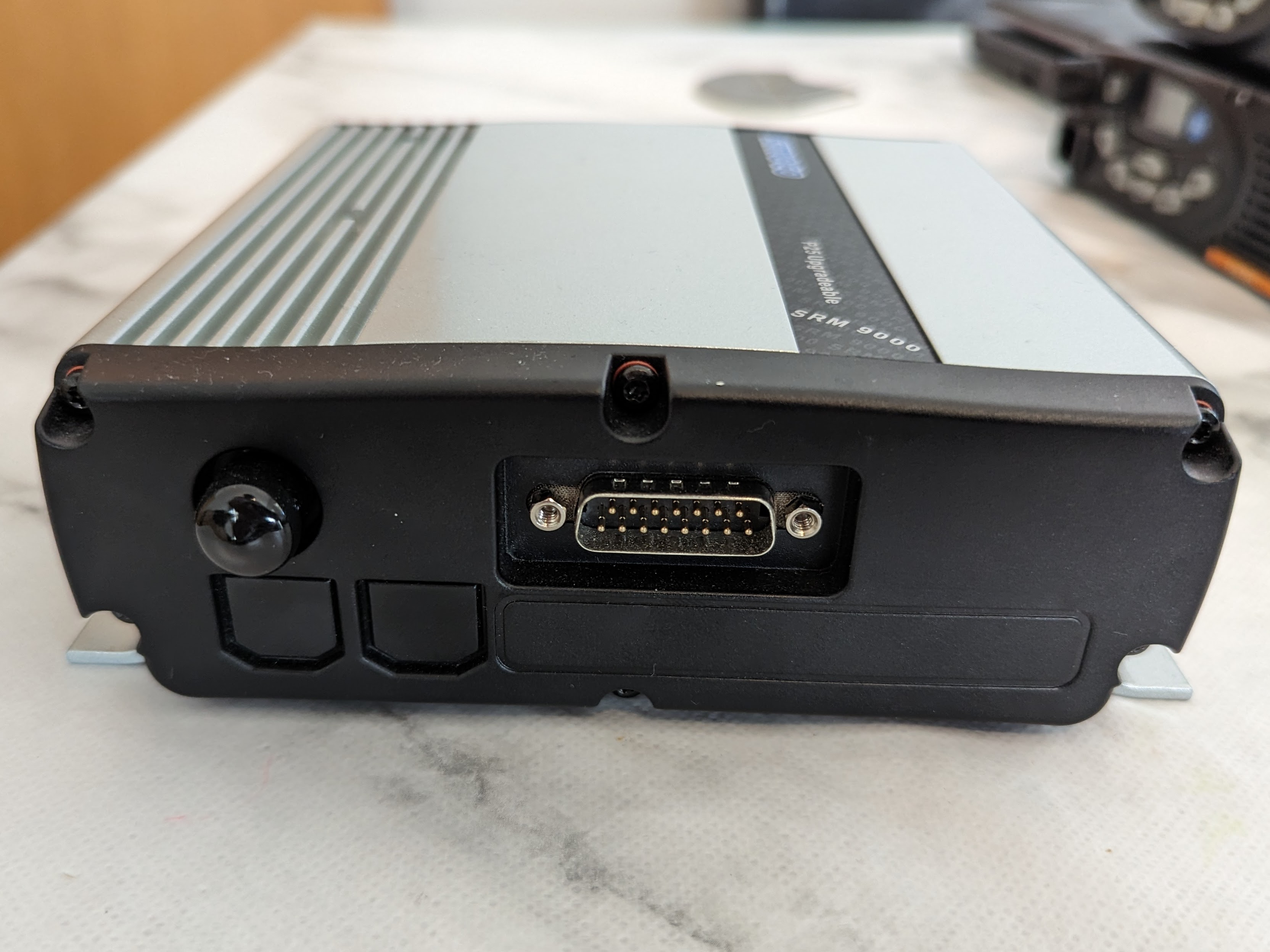
Rear of the radio showing the DB15 Power and accessory connector and BNC connector fitted with a dust cap:
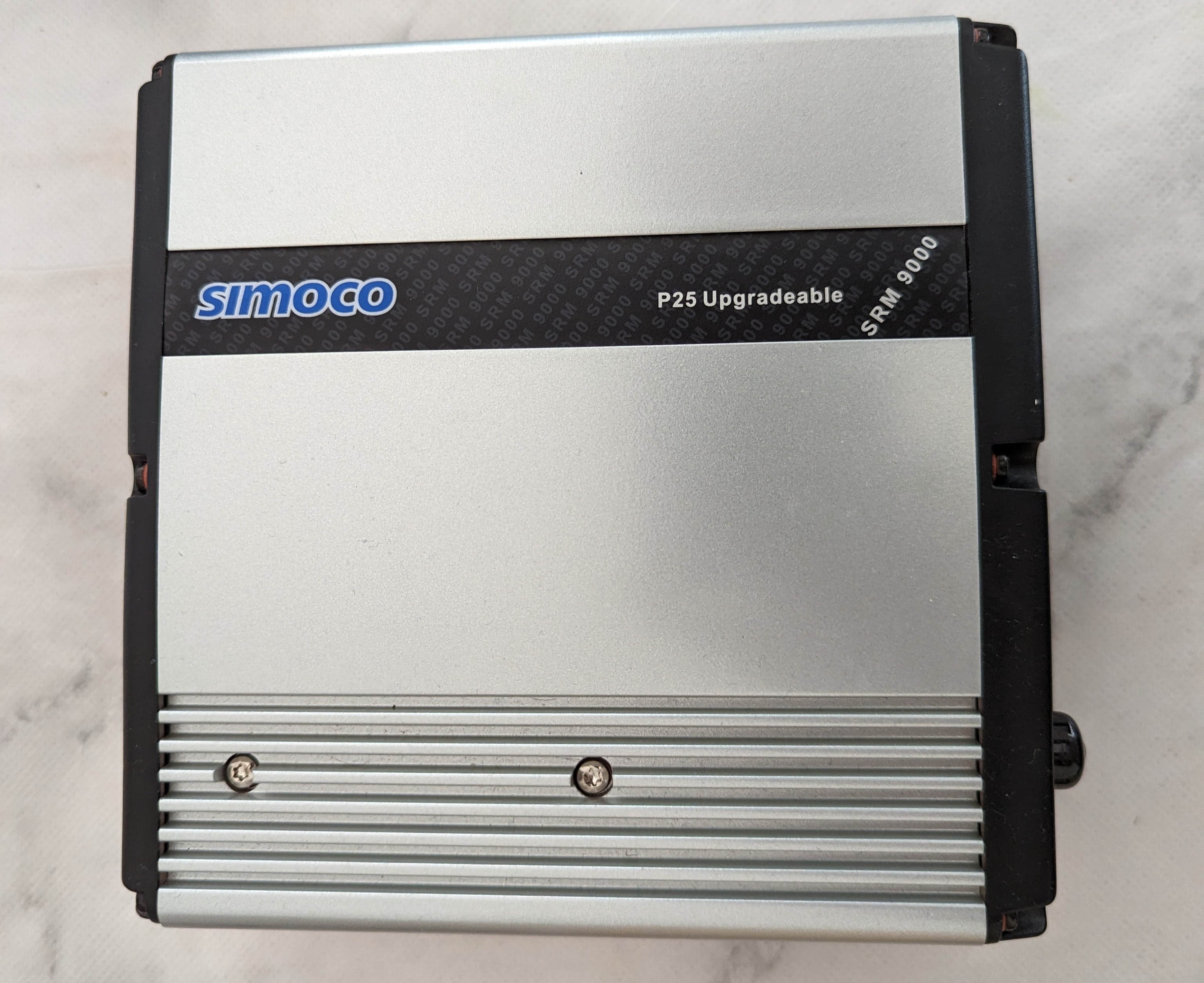
Top of the radio. Note the Blue Simoco branding and “P25 Upgradeable” text might indicate its a Revision 9 PCB, but thats TBC
Modifications
Revision 9 PCB
Note: The modifications documented below improve performance at 9600 baud, but it's still unsatisfactory. They aren't required for 1200 baud operation and remain here for posterity.
Required Tools
You will need:
- Torx T10 - For the screws the secure the endcaps and PCB.
- Soldering Equipment - To remove resistors and add the bodge wire
You might need:
- Heatsink Compound - To reapply to the PA after removal.
- 330 Ohm 1005 SMD resistor - To replace a removed resistor at a later date
- 220 Ohm 1005 SMD resistor - To replace a removed resistor at a later date
Disassemble the Radio
With a T10 Torx driver, unscrew the 12x black screws securing the plastic end caps to the aluminium body, and remove them. You will then need to slide out the Simoco label to expose 3 more screws underneath. Undo the 5 screws on the top of the radio and remove them, you should be able to then slide the PCB out in the direction of the RJ45 Mic connector to avoid smearing the heatsink compound on the inside of the radio. Once you've slid it out you can remove the PCB from the aluminium carrier. Watch out for the heatsink compound!
Transmit
Denis G4KWT came up with a mod for the Rev8 PCBs to improve Tx performance. Matthew 2E0SIP then updated it for the Rev9 PCB. The mod skips some stages of the audio chain to improve baseband performance.
Firstly remove the 220 Ohm resistor on the bottom of the board that connects Pin 14 to the rest of the circuit. A blob of solder on the end of the soldering iron will remove it quite quickly. It's unlikely you'll see it again, so purchase some replacements if you're likely to want to reverse the mod in future.
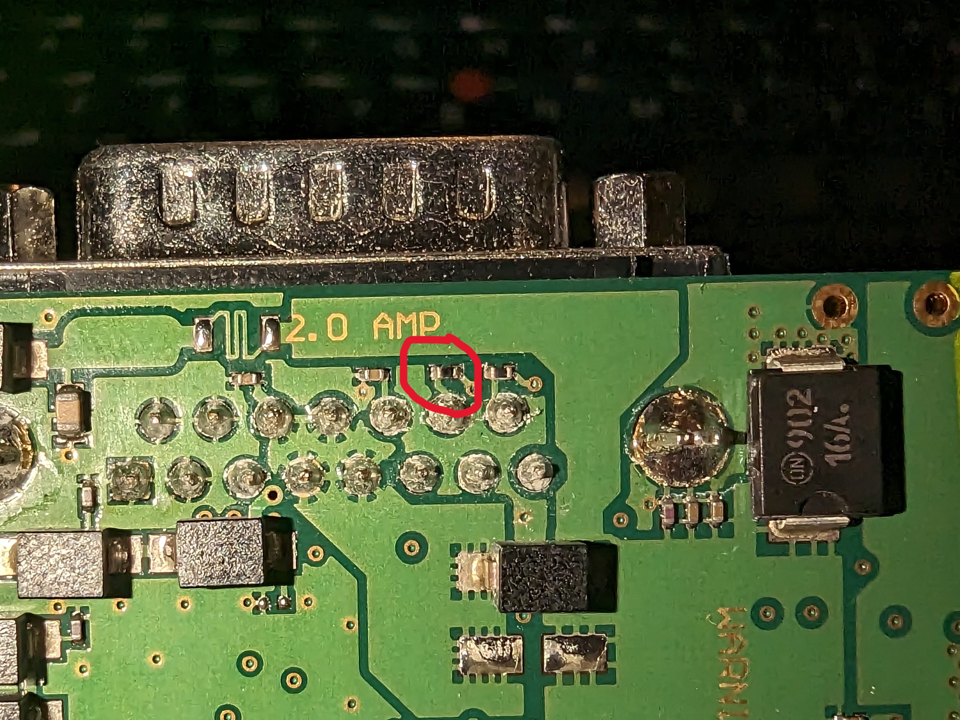
With the resistor removed, you can now add the bodge wire between a resistor on the board and the now disconnected pin 14. A conveniently placed hole in the board allows you to route the wire from one side of the board to the other fairly neatly.
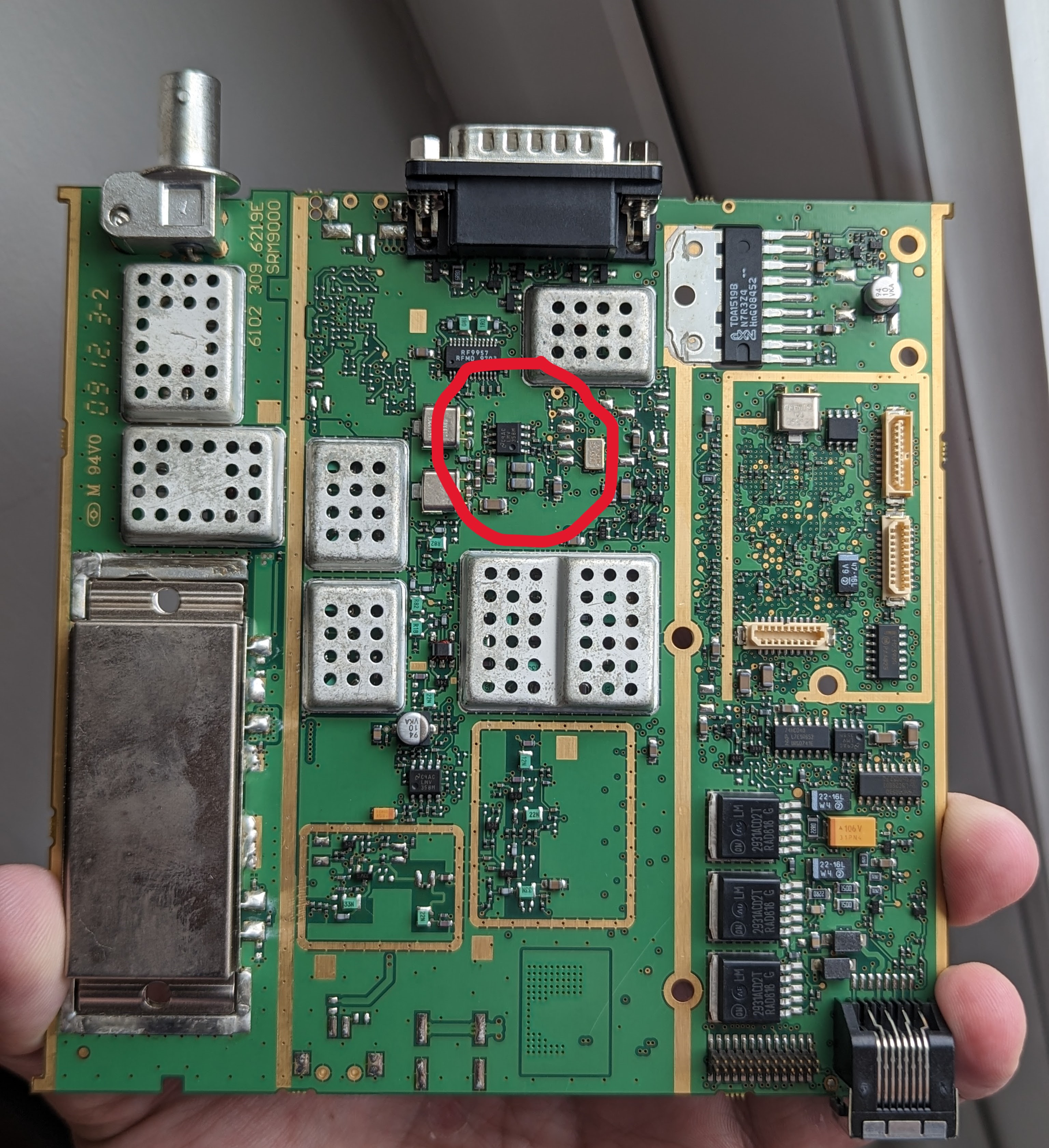
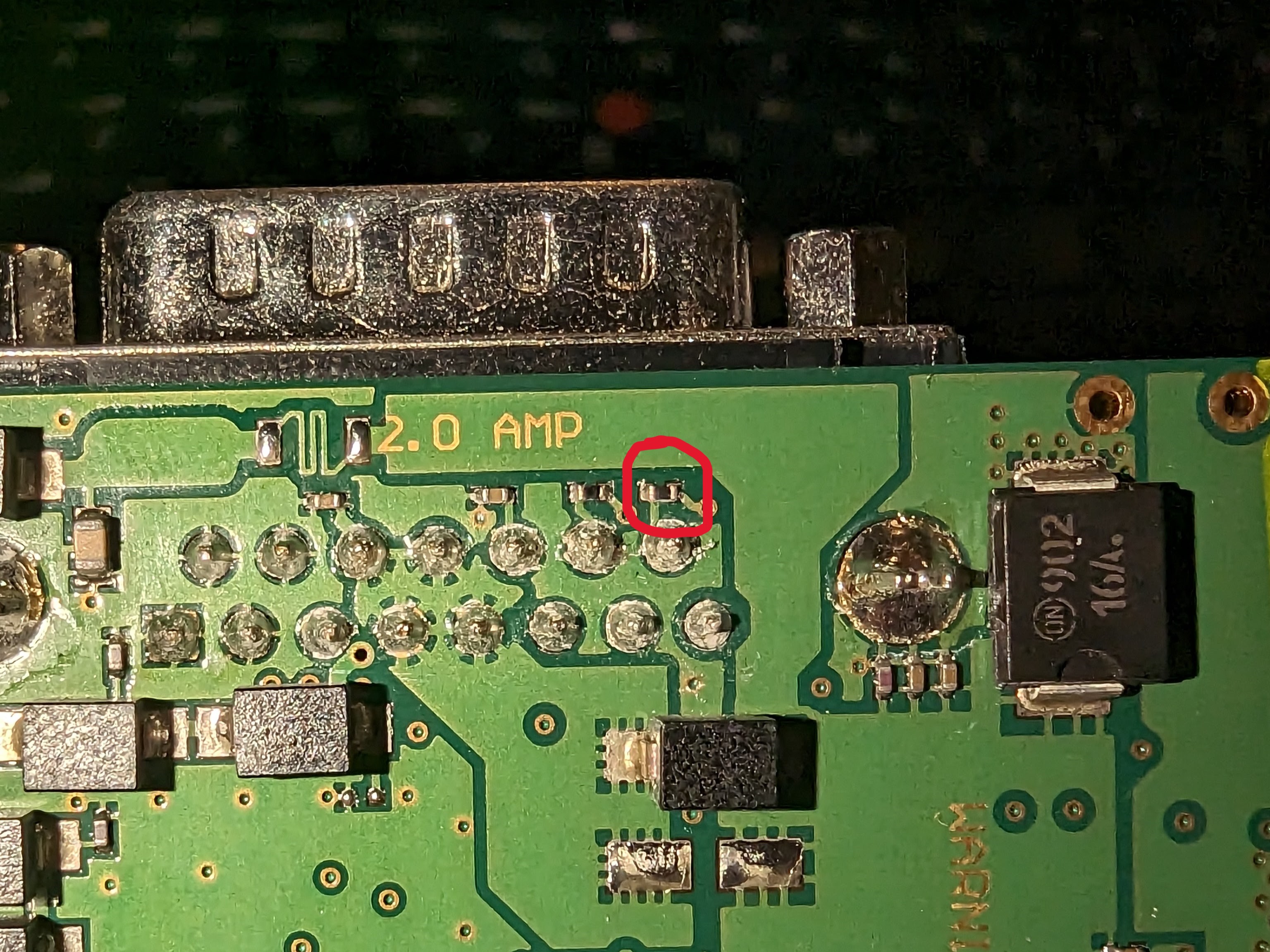
The area the Tx mod is applied to:
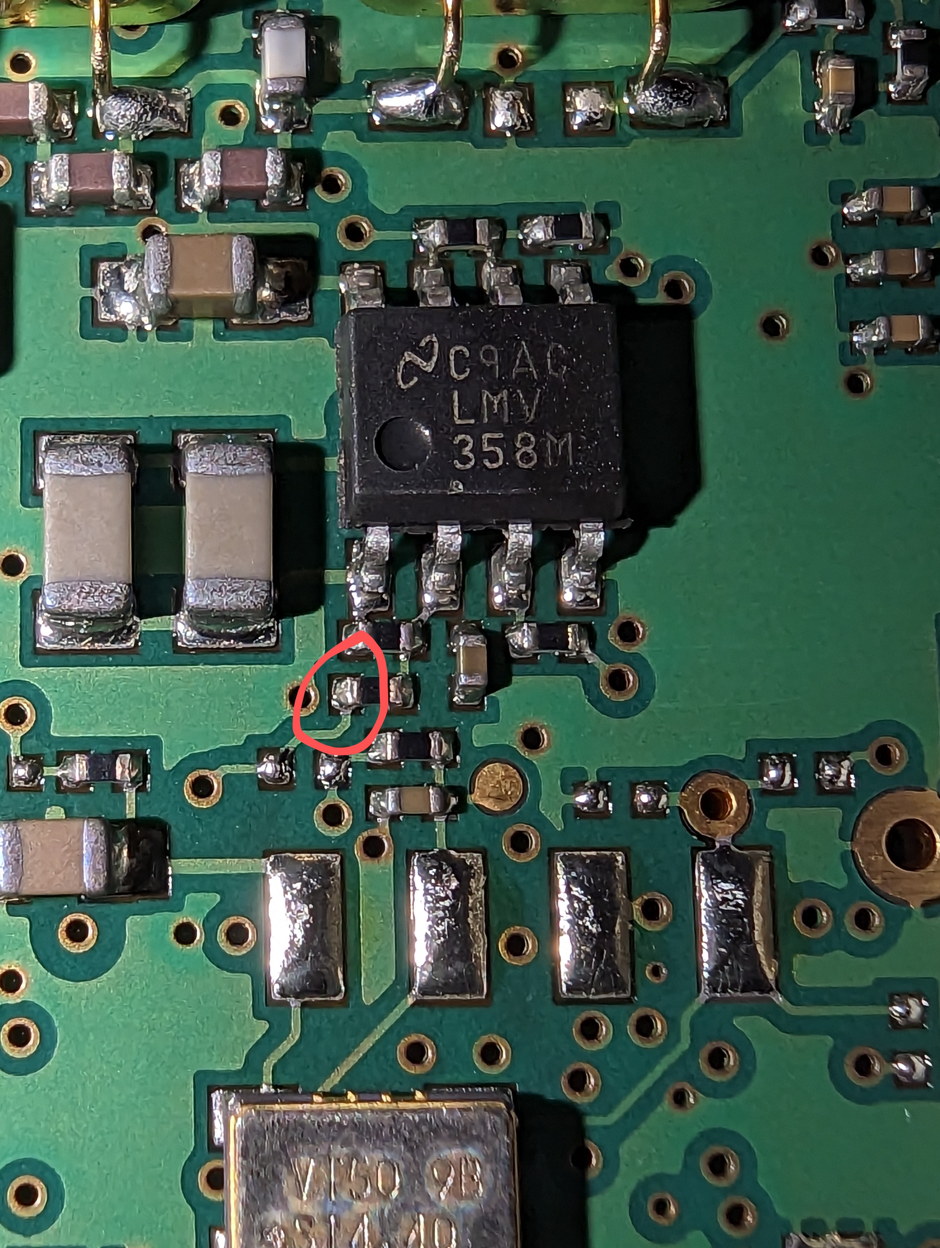
Close up of where one end of the bodge wire needs to be added:
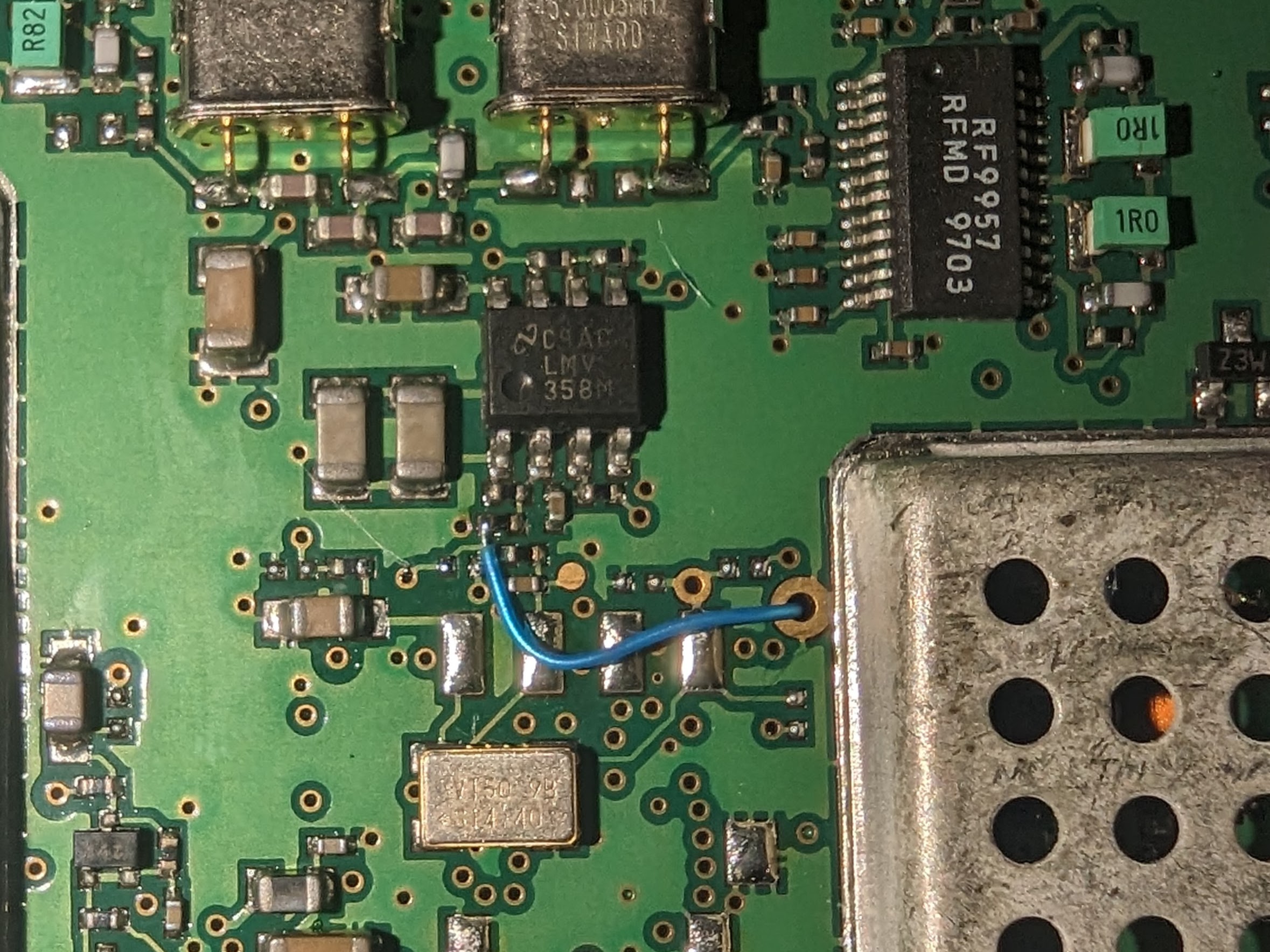
Bodge wire routing on the top side of the board:
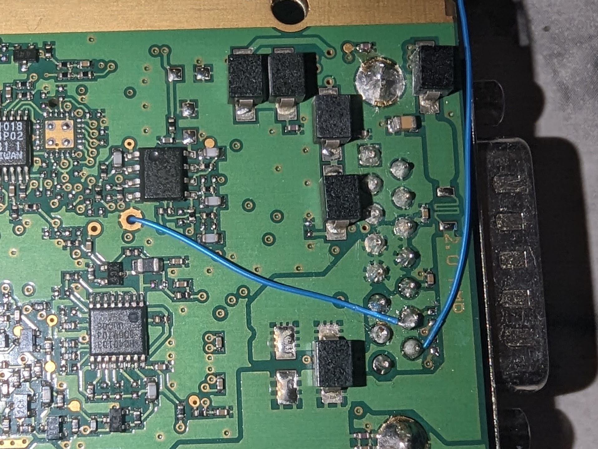
Completed bodge wire connected to Pin 14 (Rx mod also shown):
Receive
Didz / rickzero64 on the Simoco Mailing List suggests a modification to the Audio Output to improve performance for MMDVM setups. The mode effectively duplicates one of the pins from an internal options connector to the external connector on the read of the radio. This example is for the TU UHF model but may apply to others.
Firstly remove the 330 Ohm resistor on the bottom of the board that connects Pin 15 to the rest of the circuit. A blob of solder on the end of the soldering iron will remove it quite quickly. It's unlikely you'll see it again, so purchase some replacements if you're likely to want to reverse the mod in future.
With the resistor removed, you can now add the bodge wire between a capacitor on the board and the disconnected pin 15. Note that the outer aluminium enclosure has separators that run the full length of the gold strips on the PCB, so the wire must be routed from the capacitor to the edge of the board before turning to connect to the DB15 connector. If you're not careful this wire can snag when pushing the PCB back into the enclosure, so secure it with kapton tape or possibly glue in a couple of locations.

Finally reassemble the radio, replacing the heatsink compound if required, and program it with the settings below to make it think its got an options board inside:

Programming
To program the radio you will need a proper programming lead or a TTL level USB UART adapter. Check the pinout section below to wire it up. I used the “FPP V5.86” programming software and it appeared to run fine on Windows 11. The first time you program the radio it'll also update the firmware.
I was able to read from the radio without a Mic / Control Head, or doing anything in particular to switch the radio “ON”, however I got the warning “Radio does not contain a PMR configuration”, presumably because it's new out of the box. Once I created a new config, it programmed fine.
TODO: Add actual programming settings once properly tested
Pin Outs
Microphone / Handset Connector
Note The Simoco documentation numbers the pins opposite to the general standard used for RJ45 connectors.
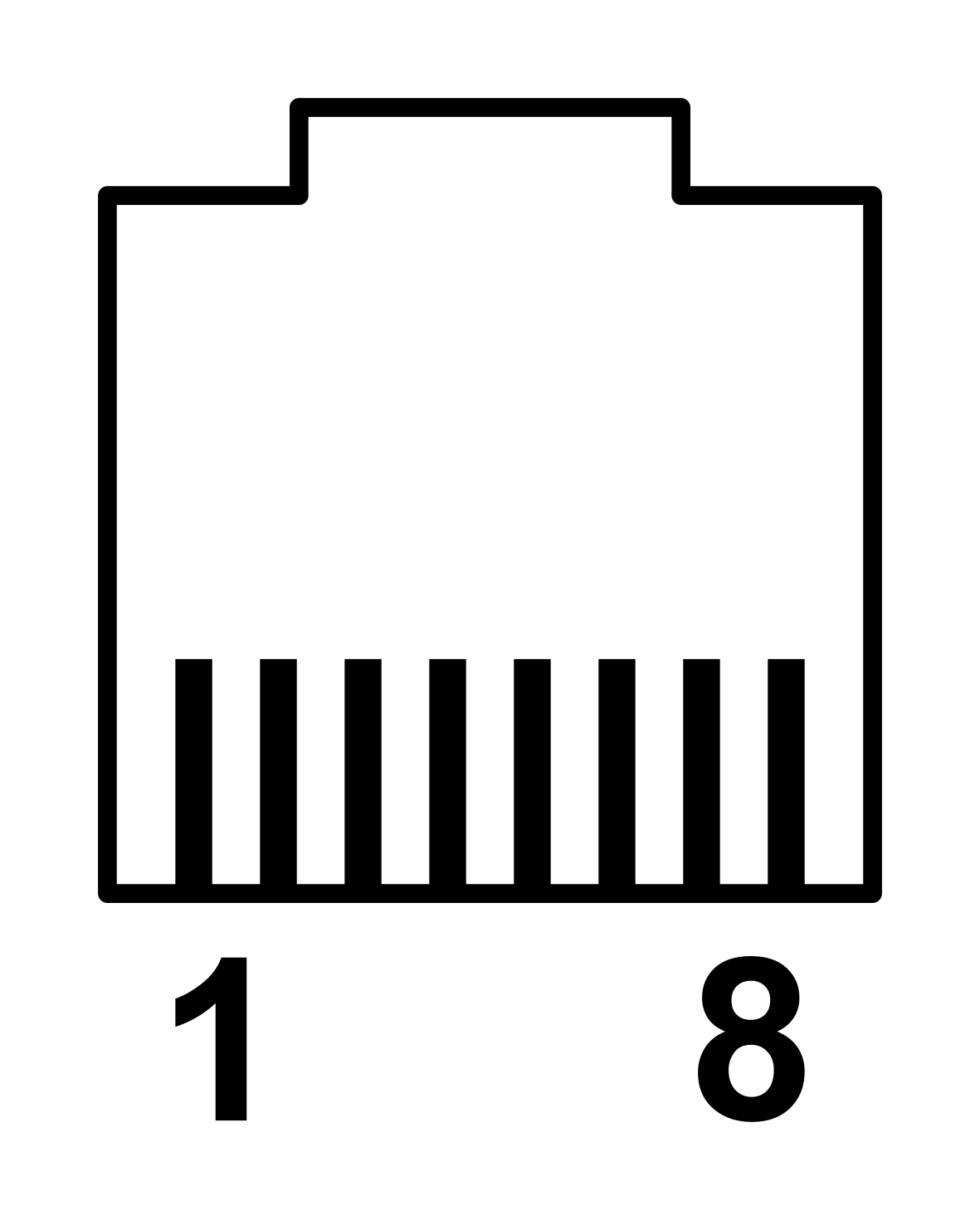
| Name | Pin | Comment |
| Tx-Data | 1 | Output (TTL Level). Low = 25mA sink to GROUND, High = 2k2 Ohm pull-up to 5v via a series diode. Diode Clamped to -0.6v & 5.6V |
| Rx-Data | 2 | Input (TTL Level). Low < 0.5V, High > 2.5V. Internal 6k8 Ohm Pull-Up to 3.3V. 780 Ohm in series with diode protection clamped to -0.6V & 3.3V |
| On/Off Input | 3 | Input. Low <5V, High > (Supply Volts - 1.5V) or O/C. Internal 6k Ohm Pull-Up to Supply Voltage. Diode Clamped to -0.6V & 18V. |
| Mic Ground | 4 | Connected internally to Ground. |
| +13.8V | 5 | Switched + Supply Voltage. 250mA Max Current. |
| Handset Audio (OP) | 6 | Output. AC Coupled (10uF) to 0/5V Op Amp Output. 245mV RMS (nominal) for 60% RF deviation of 1000Hz tone. 600 Ohm series Impedance, Diode clamped to +/- 5.6V. |
| Ground | 7 | Internally connected to -VE. |
| Mic Audio (IP) | 8 | Input. 40mV RMS at 1kHz = 60% RF Deviation. >1k series impedance, Diode clamped to +/- 0.6V. |
External Interface Connector
The SRM9000 has a male 15 pin D-Sub connector on the rear of the radio which is used for both power and data.
13.8v and Gnd are supplied to groups of 4 pins respectively. Individual pins on reputable D-Sub connectors are rated for up to 5A of current, so for programming and testing on low power you can probably get away with supplying power to one pin, at your own risk. Approximate current consumption is 145mA at idle.
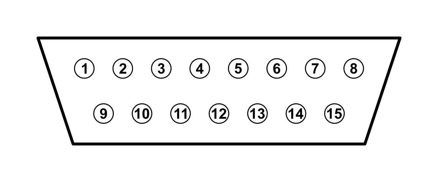
The connector, looking into the radio
| Name | Pin Number(s) | NinoTNC Pin |
| -VE (GND) | 1, 2, 9, 10 | 6 |
| +VE (+13.8V) | 4, 5, 11, 12 | N/A |
| Speaker | 6, 13 | N/A |
| General Input (PTT/RTS) | 7 | 3 |
| General Output (CD/CTS) | 8 | N/A |
| Ignition Sense Input | 3 | N/A |
| Tx Audio In | 14 | 1 |
| Rx Audio Out | 15 | 5 |