
Table of Contents
Tait TM8100 series
The Tait TM8100 series are “PMR” radios that have become popular with Amateurs due to their excellent performance, modern architecture and flexibility. VHF models can often be picked up for £20-35 on eBay if you're patient. Unfortunately UHF models are difficult to come by and cost up to £125, but the occasional bargain is still out there.
Images
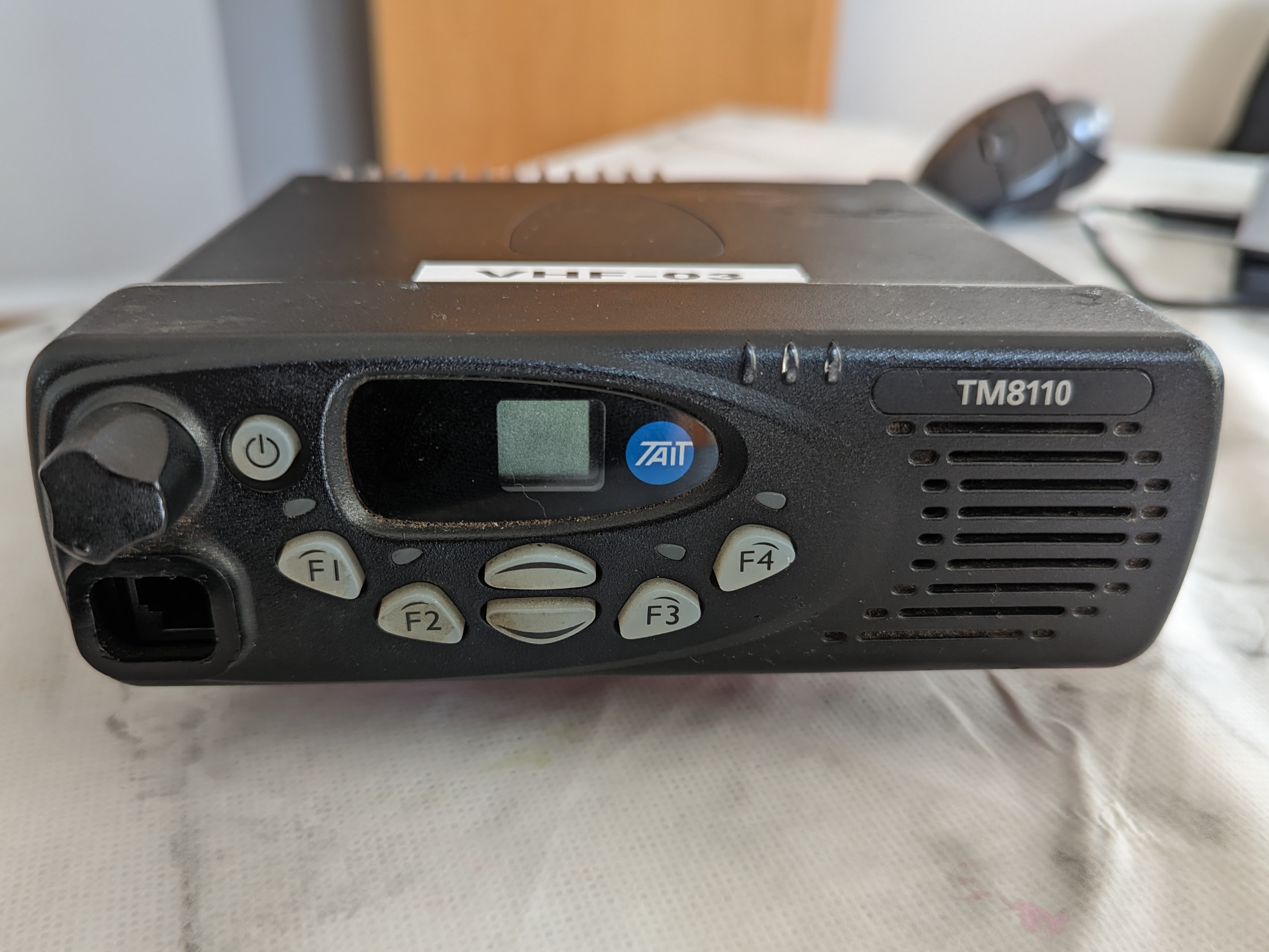
10 Channel Tait TM8110:
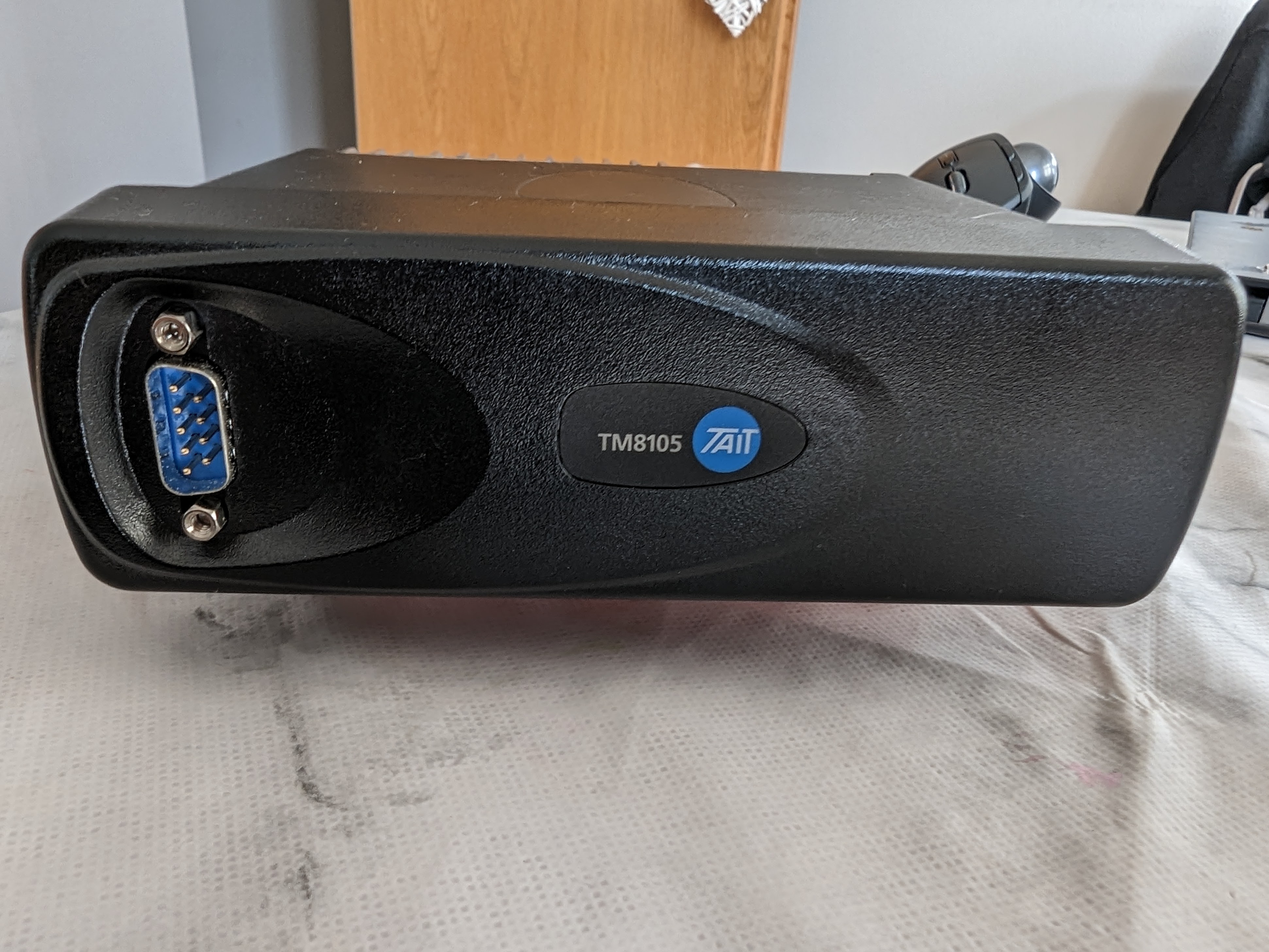
100 Channel Tait TM8105 Data Radio:
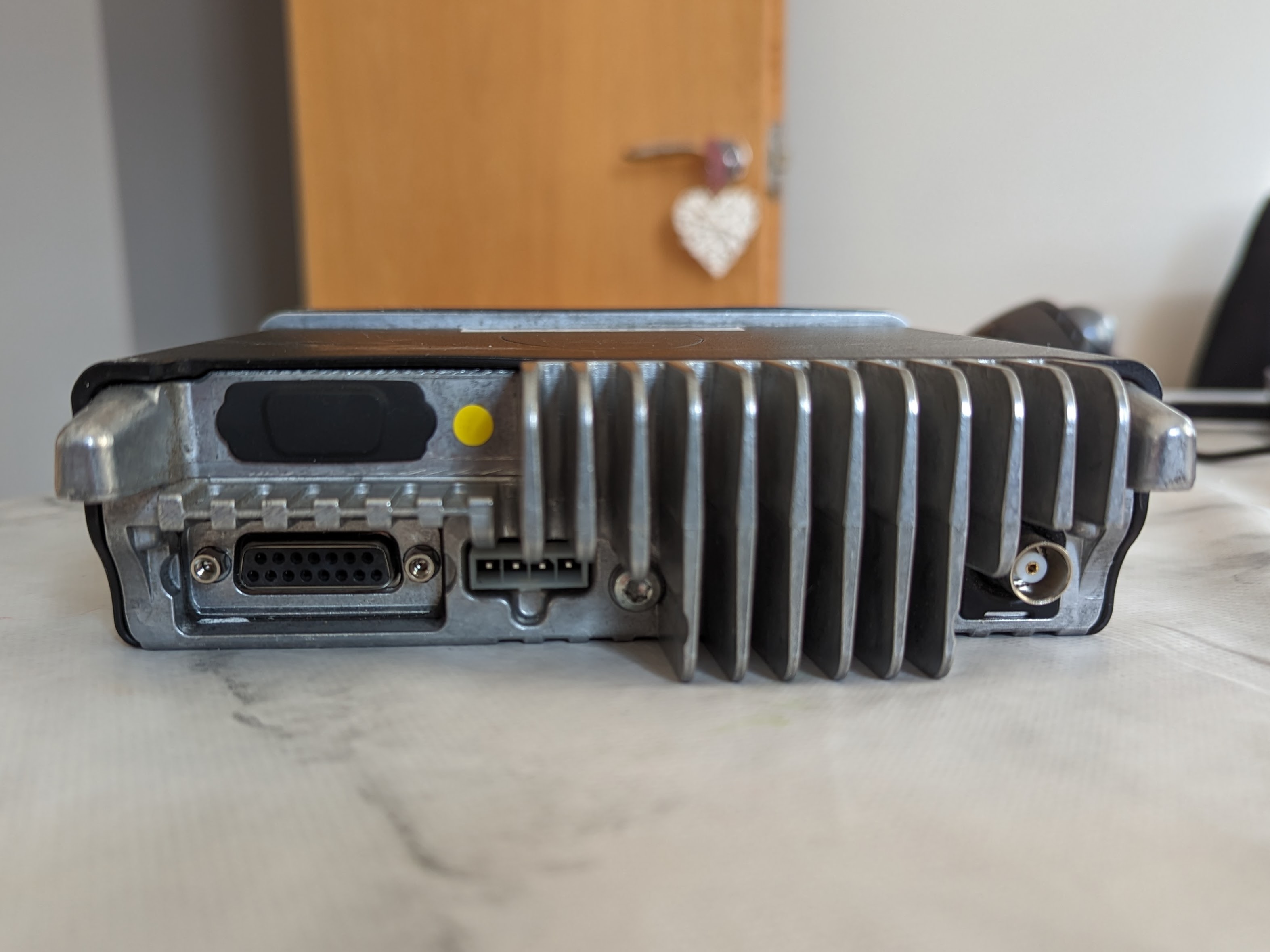
Rear of a TM8100 series radio, showing the DB15 accessory connector, power connector, BNC RF connector, and unpopulated DB9 for an optional internal options board:
Models
The TM8100 range consists of several models, although its worth noting the body is the same and the control heads can be swapped around or removed entirely.
| Model | Notes |
| TM8105 | Proper “Data” radio without a control head. Note the DB9 connector on the front is NOT a standard RS232 serial layout. |
| TM8110 | 10 channel radio |
| TM8115 | 100 channel radio |
| T-S8107 | 10 channel radio with epoxied DB15 socket. Internal connector confirmed to have programmable pins functionality. |
They are available in the following frequencies. The radio identification or frequency range can usually be found on a sticker on the base of the radio. Watch out for the C0 “Band 3” models which are outside of the amateur band. Otherwise almost all the radios you come across will be B1 VHF Models.
| Identification | Frequency (MHz) |
| A4 | 66-88 |
| B1 | 136-174 |
| C0 | 174-225 |
| D1 | 216-266 |
| G2 | 350-400 |
| H5 | 400-470 |
| H6 | 450-530 |
| H7 | 450-520 |
| K5 | 762-870 (Tx) 762-776 and 850-870 (Rx) |
Power Requirements
The radio will operate on 10.8V to 16V and RF power output is stable down to 12v.
The table below shows the relationship between RF output and DC power in. Note it may not be entirely accurate, but should be good enough.
| Watts Out | Amps In |
| 1 | 1 |
| 5 | 1.5 |
| 12 | 2.5 |
| 25 | 3.5 |
TODO: VHF / UHF?
(From Phil M0OFX) - Idle power while receiving and squelched is around 350 to 400 mA for a Band B1 TM8105 data radio. Radios with speakers and more complex control heads will be higher. 500 mA is probably a reasonable rule-of-thumb.
Pinout
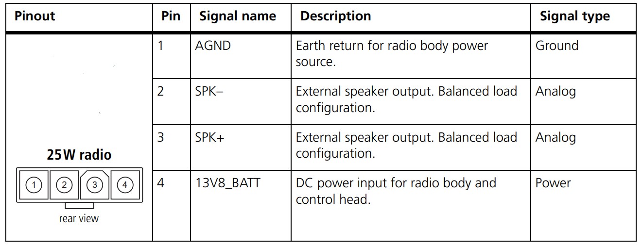
The 25 watt TM8100s use a Molex Mini-Fit Jr connector. Replacements are available on eBay, or if you wish to make your own the housing is part number 39-01-4040 and the pins are 39-00-0078.
The pinout is as follows:
There are higher power variants with the following:

brand is Positronic
DF04F00/AA - housing
FC116N2/AA - DC power pins
FC422N2/AA - speaker pins
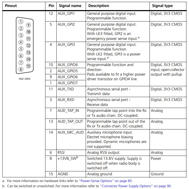
Auxiliary Connector Pinout
The simplified pinout:
| Pin | Use | Standard through-hole NinoTNC pin (9 pin D sub) | Surface-mount components NinoTNC pin (6 pin mini DIN) |
| 7 | Transmit Audio (Input) | 1 | 1 |
| 12 | PTT | 3 | 3 |
| 13 | Receive Audio (Output) | 5 | 4 (9k6) / 5 (1k2) |
| 15 | GND | 6 | 2 |


The levels on pin 13 are quite high and may over-drive some other devices. A voltage divider circuit as shown below can be used to attenuate it as needed.

A wide range of values should work. I would not use less than about 100 ohms, or more than about 100k.
The full pinout:

Programming Cable
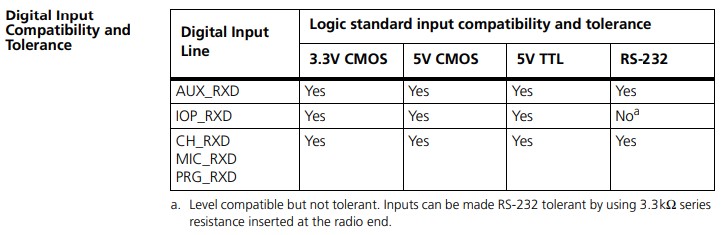
It was previously understood that the TM8100 series required inverted 3.3v serial in order to program them, however the “Computer-Controlled Data Interface (CCDI) Protocol Manual” shows that the serial Rx line is RS232 level compatible. A tear down of a commercially sold programming cable also revealed a MAX232 type chip, confirming the radios can tolerate high levels than 3.3v. This means that instead of trying to find an invertable, 3.3v serial adapter, you can just adapt an RS232 cable to the pinout of the radio assuming it'll work with receiving the lower voltages. Fortunately Most modern USB to RS232 adapters will work fine.
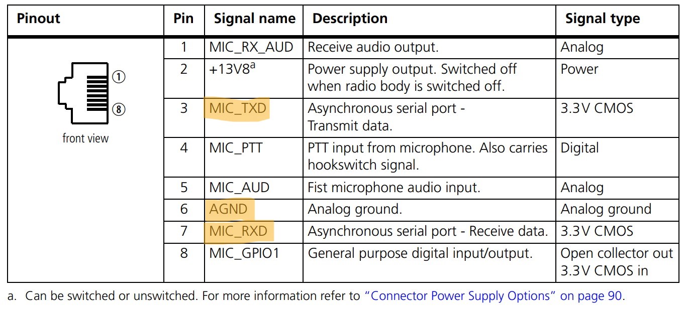
The pinout to program the radio via the RJ45 connector on the front of a TM8110 / TM8115 can be found below:
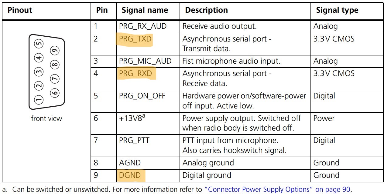
The pinout to program the radio via the DB9 connector on the front of a TM8105 can be found below:
Hints
- The help menu in the Programming Application is very detailed. Worth looking at.
- If the radio doesn't seem to respond to the software it might be configured to use a keypad mic, or use the mic port for data. Turn the radio off, trigger the read or write within the software and immediately turn the radio on. It should then beep and reboot into programming mode. It can take a couple of attempts to get the timing right, and you will have to do it each time the radio is read or written to.
- If you've got a radio that's already programmed, it's best to start with a fresh configuration rather than reading from the radio and making changes, to avoid buried settings causing problems later down the line. The programming application will start with a fresh factory default config each time its opened.
- To upgrade the radio firmware see Tait TM8XXX - Firmware upgrades
- For troubleshooting and repairs see Tait TM8XXX Repairs
Cleaning Tips
A lot of the units you'll purchase will be well used, often ex-Taxi. This can lead to some unsavory buildup of the smoker and dirt kinds which can penetrate into rubbers and leave a residue around the radio.
When cleaning the radio, you might wish to follow the basic notes outlined below:
Head Unit
- Remove the head unit by prying gently along the bottom edge between the seal and head unit plastic (page 34 Fig. 2.1 - TM8100 service manual)
- Pull off the volume knob (this will separate easily with a firm pull, and will leave a metal retention spacer either on the spoke or in the knob. Don't lose this!) and release the three clips on the PCB retainer in the head unit (page 134 Fig. 6.4 - TM8100 service manual), removing the PCB and speaker from the assembly. Take care to not disturb the exposed LCD as this will mis-aslign the zebra contact strips.
- Remove the button membrane which may contain lots of dirt buildup. Remove the 4 plastic light pipes from the membrane, wipe them clean and set them safely aside. They are keyed in two directions, both which side of the membrane they sit on (square vs round) and orientation (teardrop shape) so you cannot re-insert them wrong without it fighting you.
- Use a flat object such as a screwdriver to peel away and discard the felt sticker in the front plastic covering the speaker grille. This hides and sticks to dirt buildup which is practically impossible to clean away even using soap and water. This will not affect audio performance.
- Use warm, soapy water and a toothbrush to scrub the speaker grille and inner button holes of the front plastic toroughly, as well as around the rest of the inner plastic. This is safe to submerge. Rinse and ensure dried (a hairdryer on low here can help).
- Use warm, soapy water and a disposable cloth and toothbrush to gently clean the button membrane. Take care to not rub off the symbols, and do not scrub the black pads on the back as these are conductive contacts. This is safe to submerge. Rinse and ensure dried (don't use the hairdryer here, but pat and shake dry and leave to the side for a while). Make sure you did not miss any water in the light pipe holes or between the buttons. You can replace the light pipes once dry.
- Re-insert the membrane, click back in the PCB (make sure the speaker alignment slot is correctly positioned).
Chassis
- Remove the outer plastic casing using a flat tool of some kind (page 136 Fig. 6.5 - TM8100 service manual) and wipe it clean with an anti-bac or scrub with warm soapy water.
- Wipe down the exterior aluminium body using an anti-bac wipe, do not scrub or spray unless caution is taken not to get this in any ports. Don't worry about the lip between the top and bottom halves as this is sealed with an o-ring.
- Wipe between the fins of the rear heatsink.
- Remove the BNC and expansion port (if applicable) rubber gromets and clean these in warm soapy water.
- Gently wipe around the rubber on the power and expansion connector areas. These might need an anti-bac + flathead combo to reach.
- Remove the four screws on the top of the chassis and part the top plate from the radio (page 138 Fig. 6.6 - TM8100 service manual). Clean the o-ring seal and chassis edge by wiping.
- Check if your unit is fitted with an expansion board. If the red expansion connector is visible, the answer is no. If the answer is yes, ask us in the Discord what the board is and whether it is safe to keep. If in doubt, remove the board, as some boards will be detrimental to audio quality and will break Packet.
- Ensure the o-ring is seated correctly and will not be pinched, then replace and screw down the top plate.
Mic
- The mic is extremely simple and completely passive electronically, thus easy to disassemble. Remove the 4 rear screws and pry off the back cover.
- Unscrew the PCB and lift it gently, unplugging it from the cable.
- Very gently pull the mic out of the front plastic and set the PCB aside.
- Lift and remove the PTT plastic button and metal spring. Clean the PTT plastic button with an anti-bac.
- Remove and wipe down the rubber seal/button passthrough piece.
- Wipe the outer casings and run an anti-bac along the coiled cable. Make sure to clean the screw holes with an anti-bac and small screwdriver.
- The grille on the front of the radio is 99% for show with only a small hole for the mic itself. You can scrub this gently using a toothbrush and some kind of spray, though make sure you did remove the mic and separate away the PCB in the previous step. An anti-bac probably won't go deep enough. I used 99.9% IPA successfully but this is not advised as it can be harsh, but is very effective at removing grime.
- Reattach the rubber seal, place back in the spring and PTT plastic button, reinstall the PCB (there are wire routing channels for the mic wires), and screw the mic together.
Packet Configuration
You can download an example config file here. But better, File → Reset to Defaults, and start fresh.
That may not be possible for all radios, in which case use the Read Radio button to put the programming software into a state where the radio will take what the software is set to, and modify it as required.
Specifications
Select the band for the radio your programming, usually B1 for VHF or H5 for UHF. Note this must match the hardware you're programming.
Receiver Monitoring
Squelch Tail Extension Time: 0ms
Data, Selcall, DTMF, Two-Tone, MDC1200, Networks
Leave all at defaults (blank).
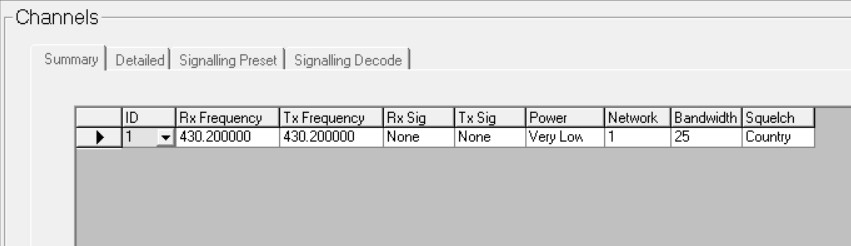
Channel Setup
Channels
The channels configuration is fairly intuitive:
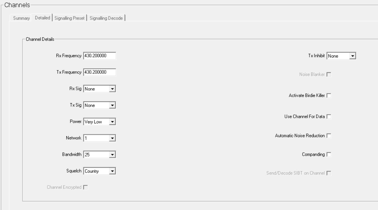
The detailed tab provides more options:
Key Settings
Key 1 - Squelch Override. Useful for debugging weak stations.
UI Preferences
Backlight Mode - Off (Optional, but worth considering for radios that just sit on a single channel to extend life / avoid it becoming a distraction)
Start-Up
Power On Mode - Power On (Ensures the radio comes back on after a power outage) / Previous State (Switches on if it was previously switched on)
PTT
External PTT(1)
PTT Transmission Type: Data Audio Source: Audio Tap In
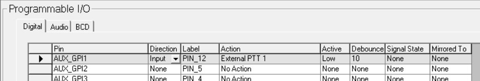
Programmable IO
Digital
Aux GPI1: Direction = Input, Action = External PTT 1
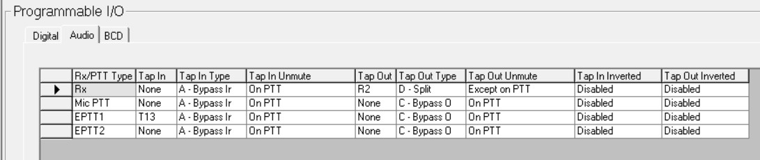
Audio
RX: Tap Out = R1, Tap Out Type = Split, Tap Out Unmute = Except on PTT
EPTT 1: Tap In = T13
Manuals
TM8100 calibration application manual
TM8100/8200 installation manual
TM8xxx hardware developer's manual (pinouts etc)
CCDI commands
ModelAndCcdiVersion: q010FE
QuerySdm: q011FD
Version: q013FB
SerialNumber: q014FA
Cctm_PaTemperature: q0450475B
Cctm_AveragedRssi: q0450635D
Cctm_RawRssi: q0450645C
Cctm_ForwardPower: q0453185A
Cctm_ReversePower: q04531959
Gps: q016F8
Display: q0270C6
Audio frequency response (mV/Hz)

Rack Ears
3d printable model for 10“ rack ears here: https://www.printables.com/model/1334607-tait-tm8110-10-inch-rack-ear
SDR Tap
Tom M0LTE, Eoin M0NVK, Jason G5RKT and Matthew 2E0SIP had some discussion on discord on where best to tap the Tait's first IF. An hupRF buffer board from SDRKits will provide a high impedance tap to avoid loading down the IF and a low impedance buffer output to drive the SDR and fits nicely into the radio.
VHF IF: 21.400MHz
UHF IF: 45.100MHz
Open up the radio and observe the beauty, it's about to be destroyed forever. First step is to remove the can on top of the IF mixer / filter stage:

To remove the filter can start snipping away with a small, flat-faced pair of sidecutters towards the corners. The corners are unbonded so you will be left with four flat-sided bits of can which can be de-soldered separately from the board.
The tap point is after the first IF amplifier filter, XF401. This is in the same location on both the VHF and UHF models:


The buffer board fits in the space left by the can and leaves enough space to solder in the tap wire.

Adding some extra shielding is probably a good idea. This little bit of copper extends up to the tap board, where the idea is to use the underside ground plane of the tap board to act as the top of the can. Can't hurt… DC / RF ground can be picked up from all over the place so I just soldered in every available spot. The shield can be soldered down to the other shield cans, and the edge meeting the board soldered back down to the pads left by the original can.
There's a dimple in the casting of the top case / cover which can be drilled out and an SMA installed:

And all finished up. I ran a power wire straight from the 12V connector, but there's probably a better place to grab power from!

(Yes, I removed the blob of solder on top of the tap board's C6 after taking the picture! Check yo board!)
I took some pains to replace as much of the shielding as possible and properly bond the tap board to every available ground - who knows if it was necessary but the receiver seems to have exactly the same performance as before.