This is an old revision of the document!
Table of Contents
Tait TM8100 series
The Tait TM8100 series are “PMR” radios that have become popular with Amateurs due to their excellent performance, modern architecture and flexibility. VHF models can often be picked up for £20-35 on eBay if you're patient. Unfortunately UHF models are difficult to come by and cost up to £125, but the occasional bargain is still out there.
Images
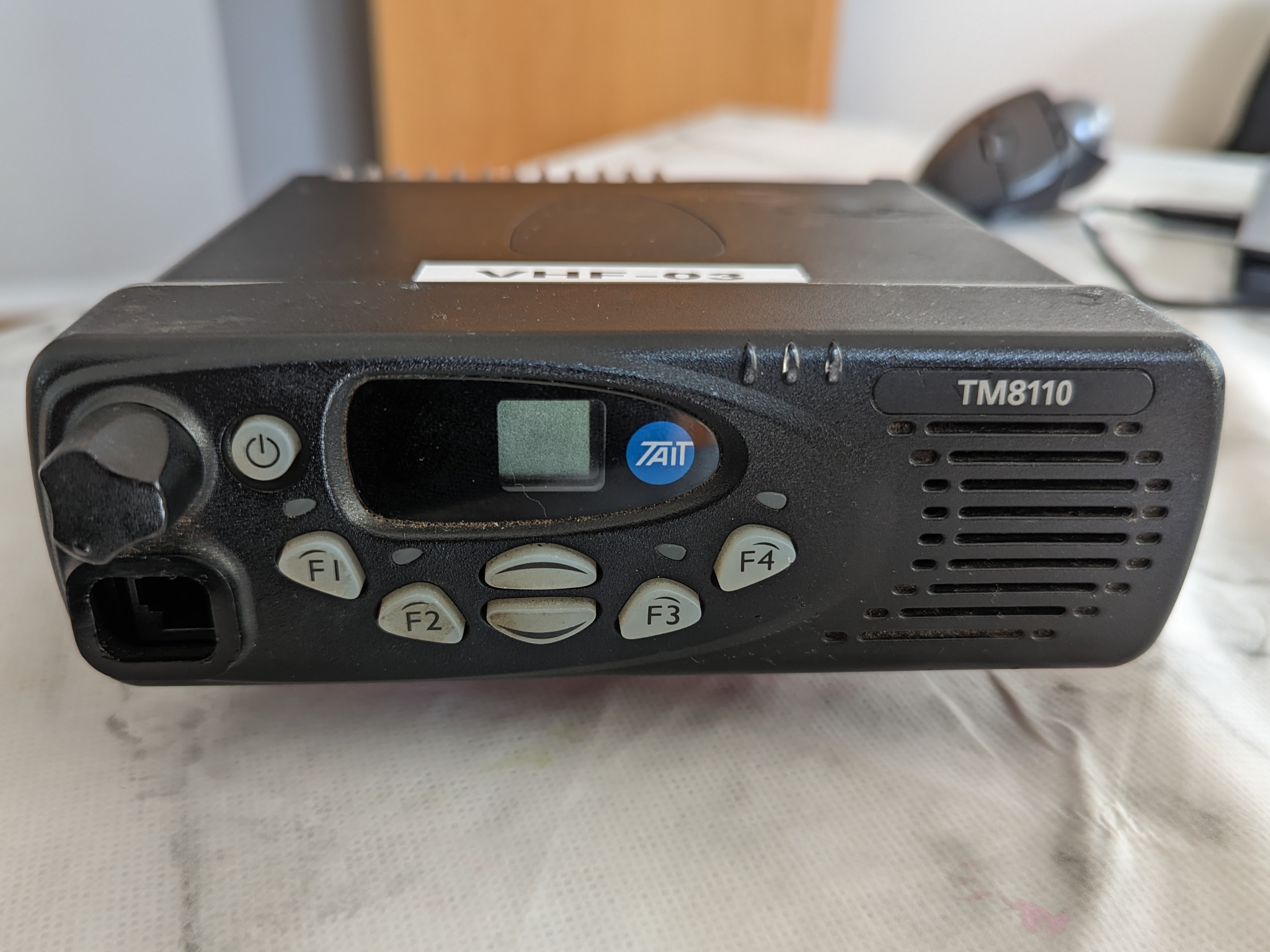
10 Channel Tait TM8110:
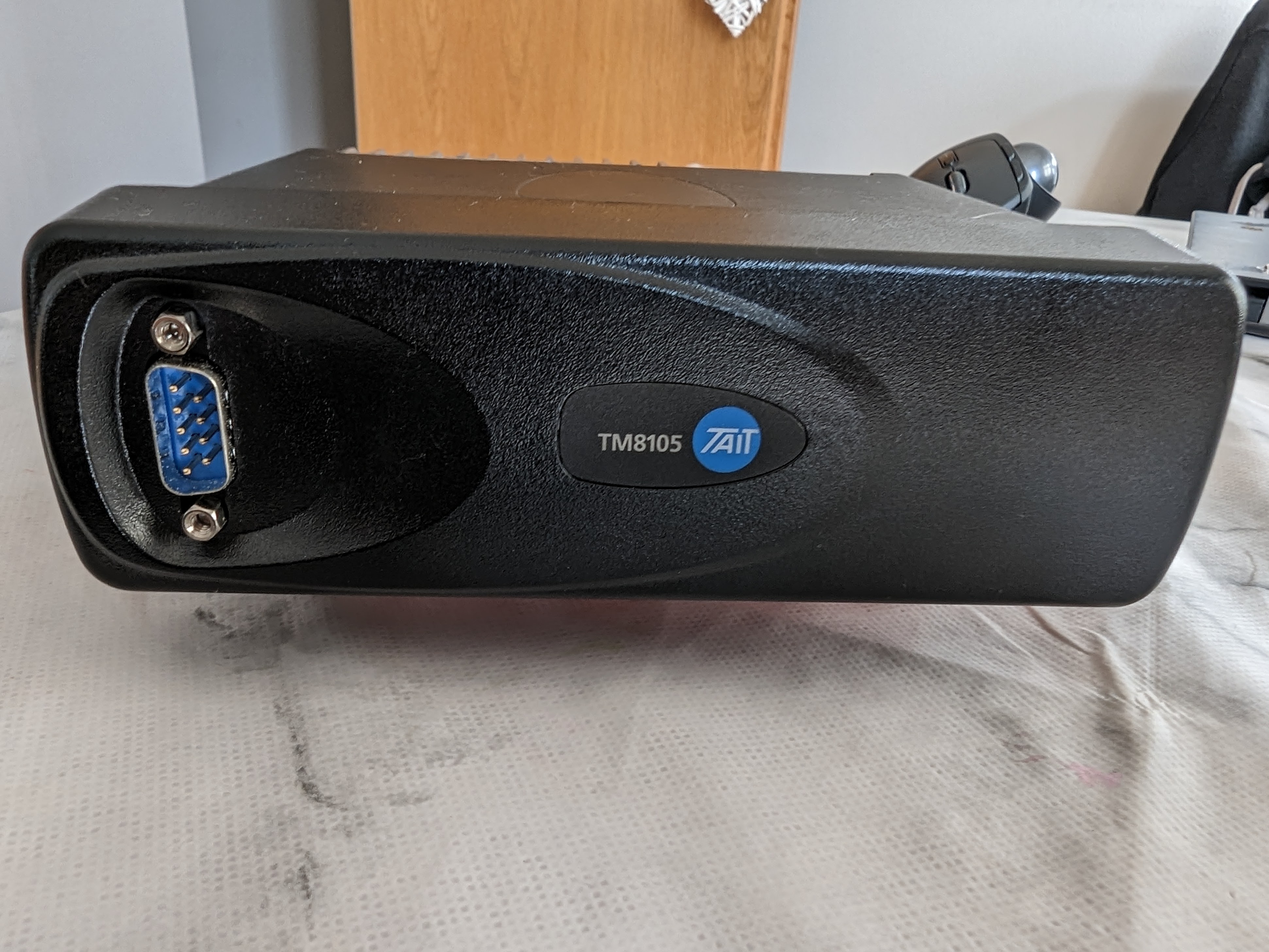
100 Channel Tait TM8105 Data Radio:
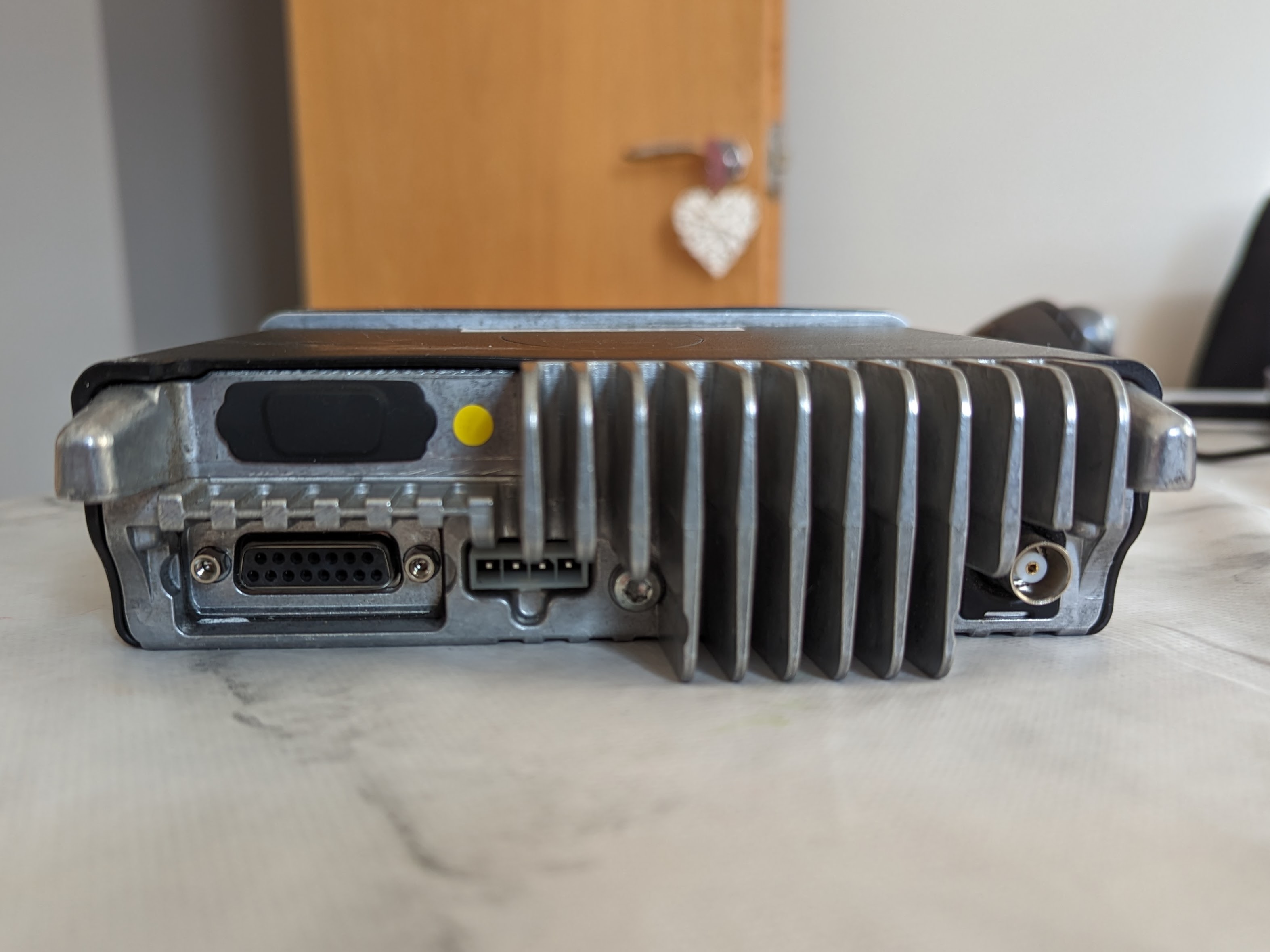
Rear of a TM8100 series radio, showing the DB15 accessory connector, power connector, BNC RF connector, and unpopulated DB9 for an optional internal options board:
Models
The TM8100 range consists of several models, although its worth noting the body is the same and the control heads can be swapped around or removed entirely.
| Model | Notes |
| TM8105 | Proper “Data” radio without a control head. Note the DB9 connector on the front is NOT a standard RS232 serial layout. |
| TM8110 | 10 channel radio |
| TM8115 | 100 channel radio |
| T-S8107 | 10 channel radio with epoxied DB15 socket. Internal connector confirmed to have programmable pins functionality. |
They are available in the following frequencies. The radio identification or frequency range can usually be found on a sticker on the base of the radio. Watch out for the C0 “Band 3” models which are outside of the amateur band. Otherwise almost all the radios you come across will be B1 VHF Models.
| Identification | Frequency (MHz) |
| A4 | 66-88 |
| B1 | 136-174 |
| C0 | 174-225 |
| D1 | 216-266 |
| G2 | 350-400 |
| H5 | 400-470 |
| H6 | 450-530 |
| H7 | 450-520 |
| K5 | 762-870 (Tx) 762-776 and 850-870 (Rx) |
Power Requirements
The radio will operate on 10.8V to 16V and RF power output is stable down to 12v.
The table below shows the relationship between RF output and DC power in. Note it may not be entirely accurate, but should be good enough.
| Watts Out | Amps In |
| 1 | 1 |
| 5 | 1.5 |
| 12 | 2.5 |
| 25 | 3.5 |
TODO: Check idle power TODO: VHF / UHF?
Pinout
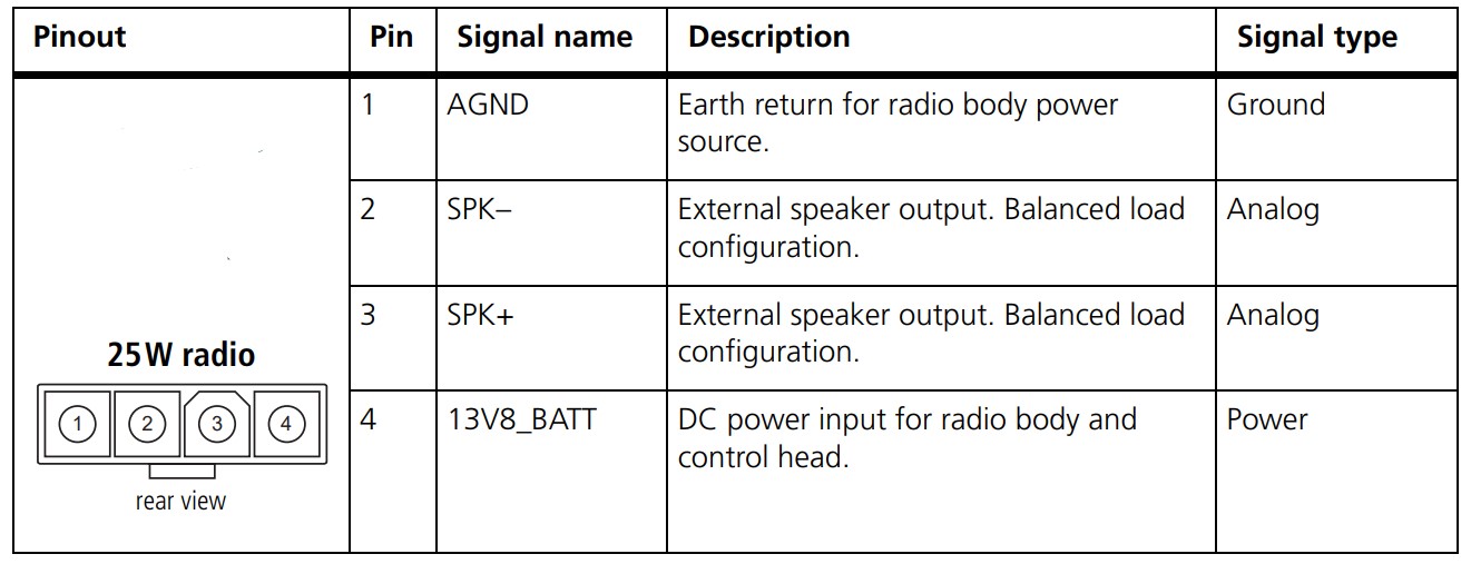
The 25 watt TM8100s use a Molex Mini-Fit Jr connector. Replacements are available on eBay, or if you wish to make your own the housing is part number 39-01-4040 and the pins are 39-00-0078.
The pinout is as follows:
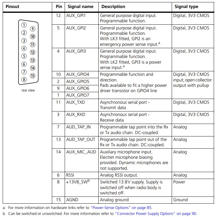
Auxiliary Connector Pinout
The simplified pinout:
| Pin | Use | NinoTNC pin |
| 7 | Transmit Audio (Input) | 1 |
| 12 | PTT | 3 |
| 13 | Receive Audio (Output) | 5 |
| 15 | GND | 6 |
The levels on pin 13 are quite high and may over-drive some other devices. A voltage divider circuit as shown below can be used to attenuate it as needed.

The full pinout:

Programming Cable
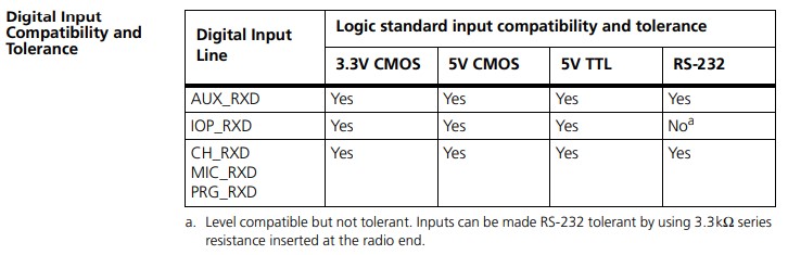
It was previously understood that the TM8100 series required inverted 3.3v serial in order to program them, however the “Computer-Controlled Data Interface (CCDI) Protocol Manual” shows that the serial Rx line is RS232 level compatible. A tear down of a commercially sold programming cable also revealed a MAX232 type chip, confirming the radios can tolerate high levels than 3.3v. This means that instead of trying to find an invertable, 3.3v serial adapter, you can just adapt an RS232 cable to the pinout of the radio assuming it'll work with receiving the lower voltages. Fortunately Most modern USB to RS232 adapters will work fine.
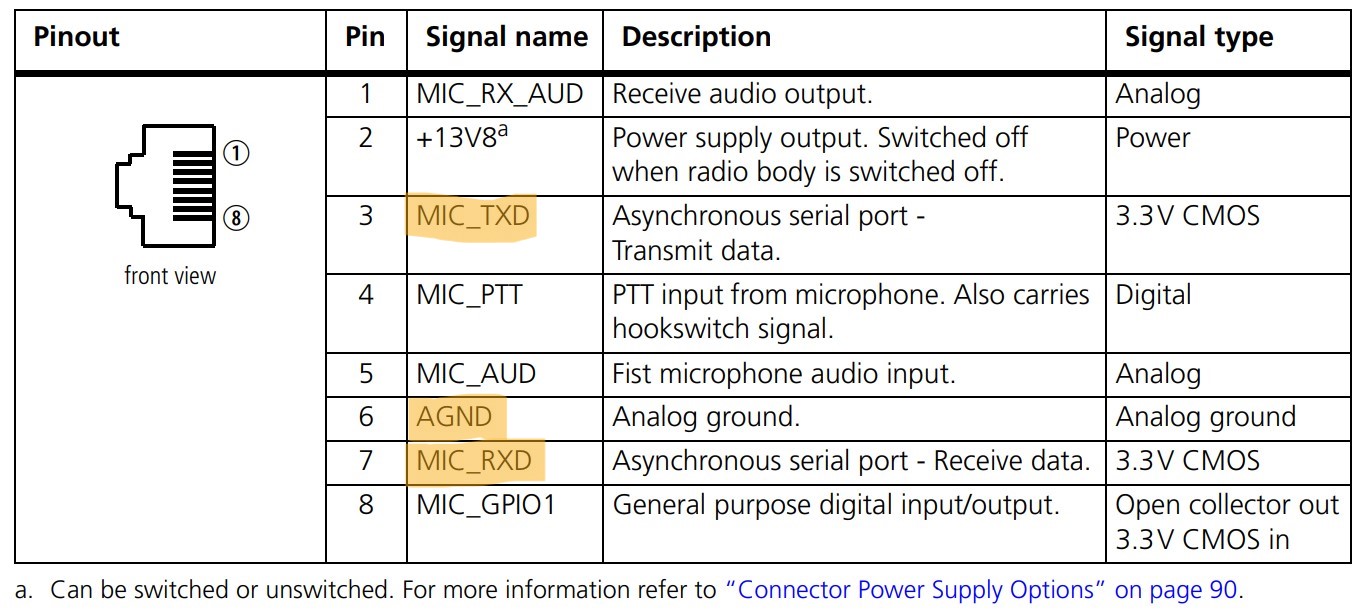
The pinout to program the radio via the RJ45 connector on the front of a TM8110 / TM8115 can be found below:
The pinout to program the radio via the DB9 connector on the front of a TM8105 can be found below:
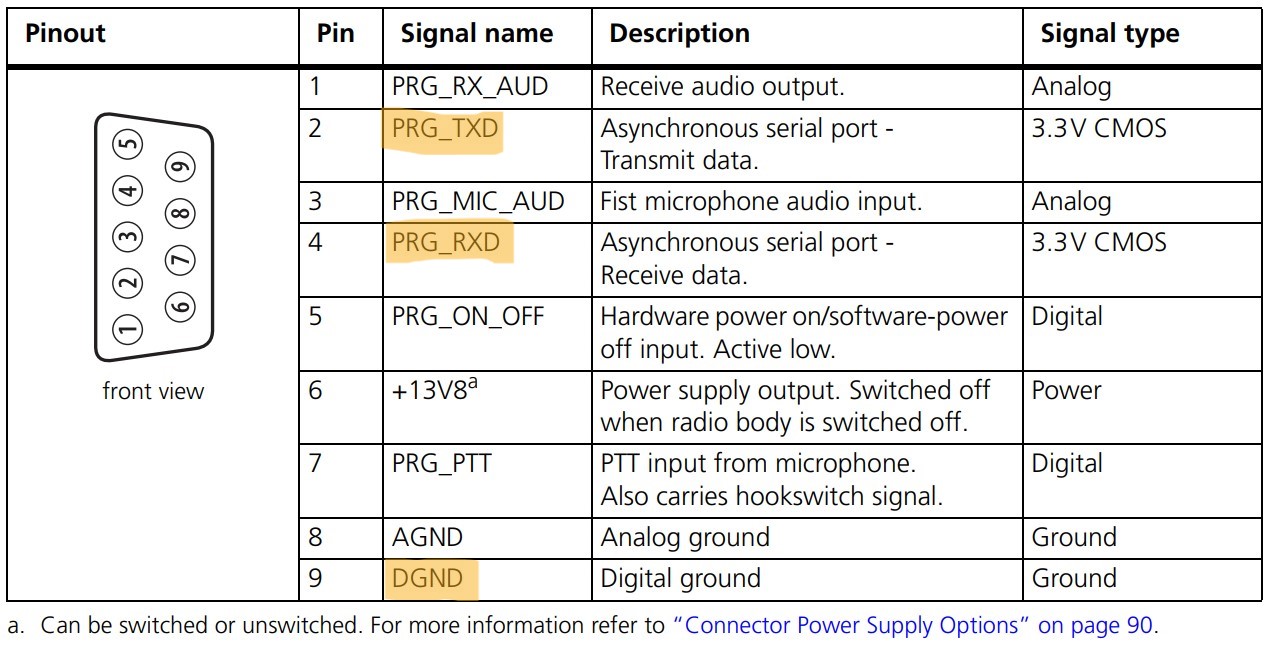
Hints
- The help menu in the Programming Application is very detailed. Worth looking at.
- If the radio doesn't seem to respond to the software it might be configured to use a keypad mic, or use the mic port for data. Turn the radio off, trigger the read or write within the software and immediately turn the radio on. It should then beep and reboot into programming mode. It can take a couple of attempts to get the timing right, and you will have to do it each time the radio is read or written to.
- If you've got a radio that's already programmed, it's best to start with a fresh configuration rather than reading from the radio and making changes, to avoid buried settings causing problems later down the line. The programming application will start with a fresh factory default config each time its opened.
- To upgrade the radio firmware see Tait TM8XXX - Firmware upgrades
- For troubleshooting and repairs see Tait TM8XXX Repairs
Packet Configuration
You can download an example config file here. But better, File → Reset to Defaults, and start fresh.
That may not be possible for all radios, in which case use the Read Radio button to put the programming software into a state where the radio will take what the software is set to, and modify it as required.
Specifications
Select the band for the radio your programming, usually B1 for VHF or H5 for UHF. Note this must match the hardware you're programming.
Receiver Monitoring
Squelch Tail Extension Time: 0ms
Data, Selcall, DTMF, Two-Tone, MDC1200, Networks
Leave all at defaults (blank).
Channel Setup
Channels
The channels configuration is fairly intuitive:
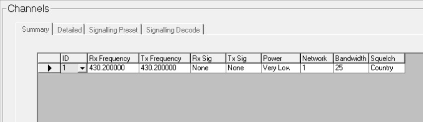
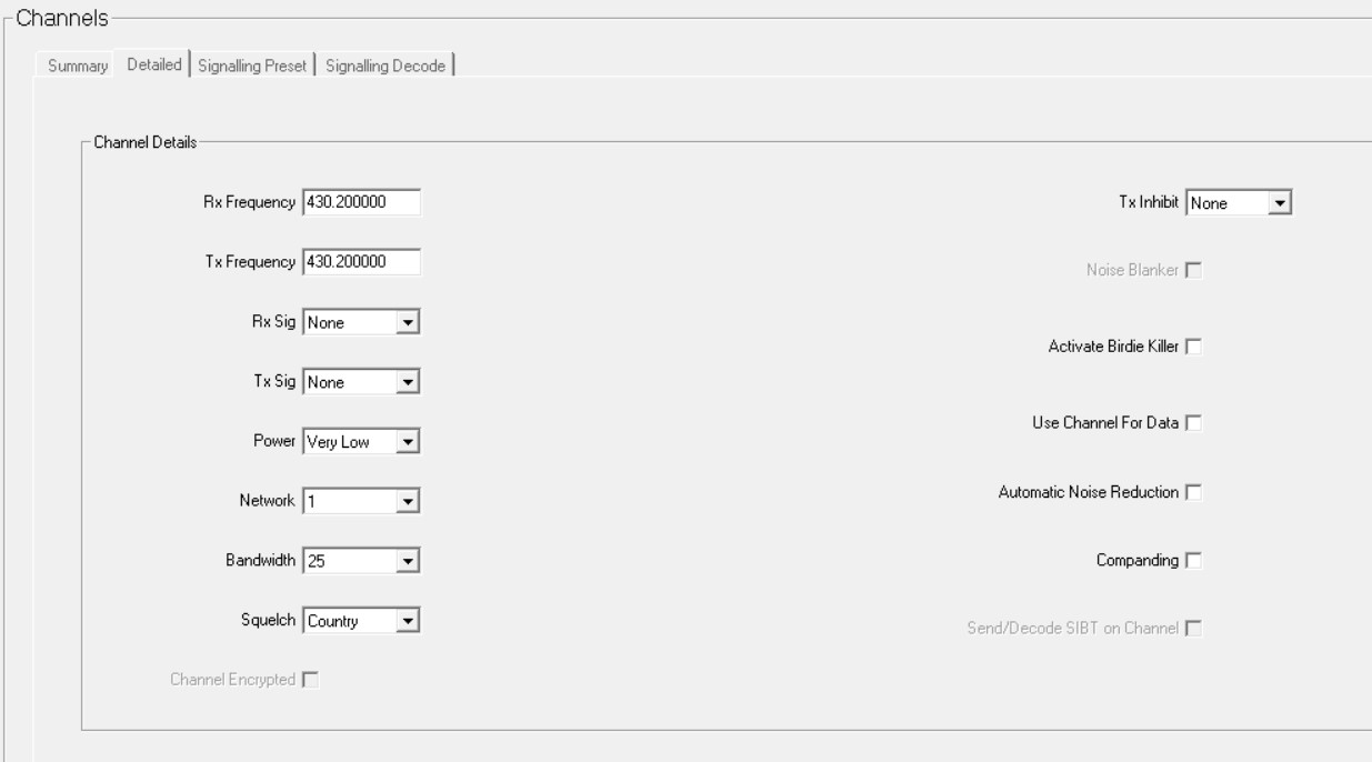
The detailed tab provides more options:
Key Settings
Key 1 - Squelch Override. Useful for debugging weak stations.
UI Preferences
Backlight Mode - Off (Optional, but worth considering for radios that just sit on a single channel to extend life / avoid it becoming a distraction)
Start-Up
Power On Mode - Power On (Ensures the radio comes back on after a power outage) / Previous State (Switches on if it was previously switched on)
PTT
External PTT(1)
PTT Transmission Type: Data Audio Source: Audio Tap In
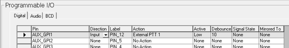
Programmable IO
Digital
Aux GPI1: Direction = Input, Action = External PTT 1
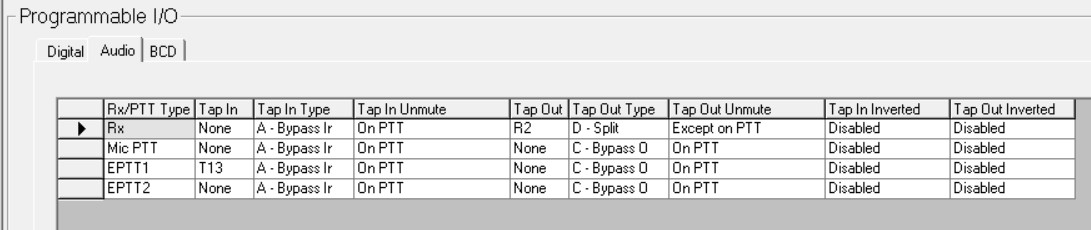
Audio
RX: Tap Out = R2, Tap Out Type = Split, Tap Out Unmute = Except on PTT
EPTT 1: Tap In = T13