
Table of Contents
WAOARC 2025 WSPR Kit Build - Construction Guide
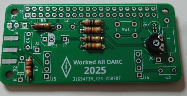
This guide will walk you through putting the WSPR Hat Kit together.
Please ask in the #waoarc-kit channel on Discord if you have any issues or questions.
Scan QR code to open this guide on mobile.

Click here if you were looking for WAOARC 2025 WSPR Kit Software Preparation Guide

Prerequisites
In your kit, you should have received the items in the table below. Please check you have everything before you begin:
| 1x 20k variable resistor | 1x 47uf 16v Electrolytic Capacitor | 2x 4-pin sockets |
| 1x 47Ω resistor (Yellow Purple Black Gold) | 3x 100nf Capacitor marked BC 104K | 1x 40-pin socket |
| 1x 20KΩ resistor (Red Black Orange Gold) | 1x BS170 Small Signal MOSFET | 15cm fine enamelled copper wire |
| 1x 1Ω resistor (Brown Black Gold Gold) | 1x LED (orange diffused) | 1x SMA Edge-mounted socket |
| 1x 15KΩ resistor (Brown Green Orange Gold) | 1x 1N4148 Small Signal Diode, 100 V, 150 mA, 1 V | |
| 1x 270Ω resistor (Red Purple Brown Gold) | 1x Push button momentary switch | |
| 1x 2KΩ resistor (Red Black Red Gold) | 1x FT37-43 Ferrite |
The kit also requires a QRPLabs Low Pass Filter. If one was requested with your kit, it will be included in it's own ziplock bag.
Resistors
Install all the resistors and trimmer variable resistor. The board is marked to assist you.
Tip - Try to have the coloured bands in the same orientation. It looks nice.
| Reference | Component |
|---|---|
| RV1 | 20KΩ Trimmer variable resistor |
| R2 | 47Ω (Yellow Purple Black Gold) |
| R3 | 20KΩ (Red Black Orange Gold) |
| R4 | 1Ω (Brown Black Gold Gold) |
| R5 | 15KΩ (Brown Green Orange Gold) |
| R6 | 270Ω (Red Purple Brown Gold) |
| R7 | 2KΩ (Red Black Red Gold) |
Capacitors
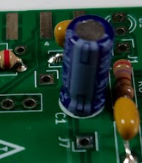
Install the capacitors.
You may find later steps easier if you leave fitting capacitor C1 until after the connectors are installed.
NOTE: C1 is an electrolytic capacitor so the orientation is critical or the magic smoke may escape. Long leg is positive, and short Leg is negative. Match the white band on the capacitor to the white area on the board
Tip - Try to orient the other capacitors so the writing faces the edge of the board and can be easily read.
| Reference | Component |
|---|---|
| C1 | 47uf 16v Electrolytic Capacitor |
| C2, C3, C4 | 100nf Capacitor marked BC 104K |
Transistor
Install the MOSFET. Make certain the direction installed matches the silkscreen on the board (Flat surface towards edge).
The pads are quite small and really close together - make sure you don't bridge them together when soldering.
| Reference | Component |
|---|---|
| Q1 | BS170 Small Signal MOSFET |
![]()
![]()
Diodes
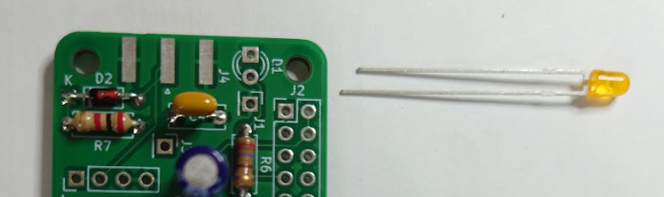
Install the diodes in positions D1 & D2.
Note the orientation of the diodes. The LED short leg must be closest to the edge of the board. The signal diode has a black stripe on one end which may be hard to see. It should be positioned closest to the edge of the board, matching the outline on the board.
| Reference | Component |
|---|---|
| D1 | LED (orange diffused) |
| D2 | 1N4148 Small Signal Diode, 100 V, 150 mA, 1 V |
Switch
Install the push button switch. The switch and it's mounting holes are slightly rectangular. It will work in either of the two possible orientations.
| Reference | Component |
|---|---|
| SW1 | Push button momentary switch |
Inductor
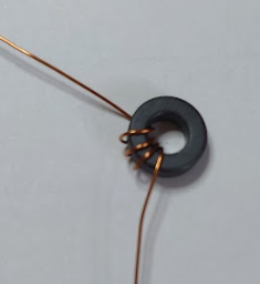
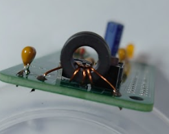
Wind the ferrite core with 4 turns of wire as shown. Each time the wire passes through the centre counts as one turn.
Note: Crop the leads longer than necessary, and scrape, sand, or heat the coating to remove it before fitting and soldering. Heating can be done with a lighter, or a very hot soldering iron.
| Reference | Component |
|---|---|
| L1 | FT37-43 Ferrite with 4 turns of wire |
 |  |
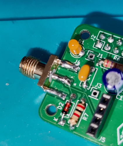
Connectors
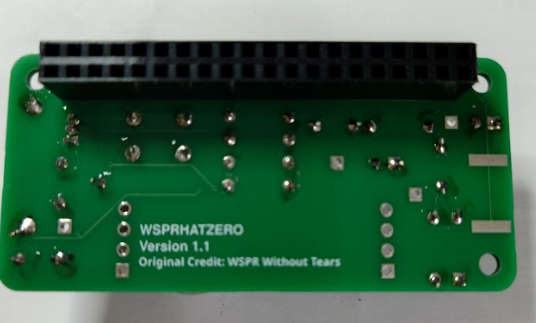
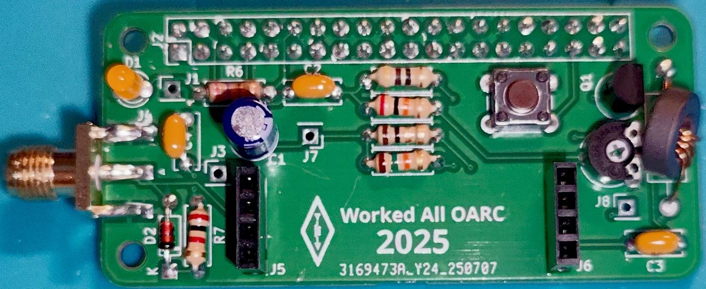
Connector J2 (the 40-pin) is positioned on the underside of the board.
WARNING: If you solder the 40-pin connector on the wrong side YOU WILL HAVE A BAD DAY. Check the picture to the right (below if on mobile).
Connectors J5 & J6 are fitted to the component side of the board.
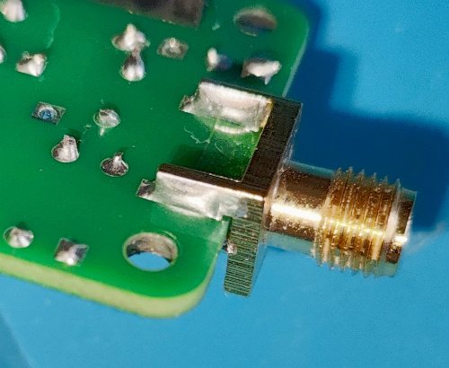
Connector J4 (the SMA socket) is positioned on the edge of the board, with the centre pin connection on the top, component side of the board. All 4 ground pins should be soldered to the board, not just the pair adjacent to the centre pin.
| Reference | Component |
|---|---|
| J2 | 40-pin socket |
| J4 | SMA edge-mounted socket |
| J5, J6 | 4-pin socket |
 |  |
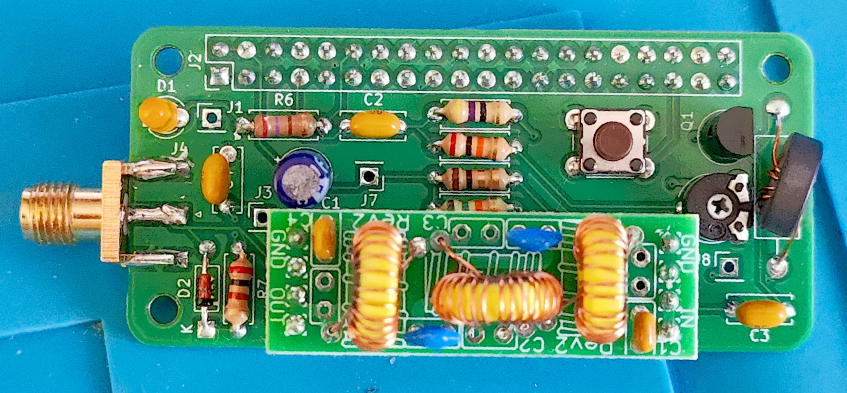
Filter Installation
When connecting your filter, (build instructions at https://qrp-labs.com/images/lpfkit/assembly_A4.pdf), you should ensure that is inserted in the correct orientation. The filter has 'IN' and 'OUT' text on the ends, and you need the 'OUT' nearest the SMA connector.
Also, holding the filter with 'IN' on the left and the toroids facing you, check for continuity between the top left and top right pins. If there is no connection, you have likely soldered on top of the coating on the wire, and have not burned it off. Remove the toroid from the board and and scrape or heat the ends of the wire to remove the coating. Fine sandpaper is easiest and works well.
Setting the pot
After completing the board & filter, you should adjust the potentiometer (RV1). Using a small cross-head screwdriver, gently rotate the pot through the entire range of motion and then set it to a central position. This is a good starting point, and for most people it will likely be fine to leave it there.
For a more exact adjustment, you can connect the output via suitable attenuation to a spectrum analyser. I used a TinySA with 30dB, 6dB, and 5dB attenuators to give a 41dB reduction. While the device was transmitting, I watched the signal on a narrow portion of the spectrum and set it for it's peak value, then widened the monitored spectrum and adjusted to reduce the adjacent harmonics.
You could also use an SDR to monitor the frequency while adjusting. You should watch for the signal to peak, then become distorted. Set the pot to a point where the signal is maximized, but distortion is minimal.
 |  |