Table of Contents
Experimental HF Waveforms
The Nino TNC (or Nino Modem) has been designed with flexibility in mind, so ongoing work includes some experimental HF data waveforms, both FSK and PSK. Below are some general guidelines on how to marry the Nino TNC to an HF radio and to set the audio levels appropriately for effective communications.
The base reference material for the Nino TNC is found at https://tarpn.net/t/nino-tnc/n9600a/n9600a_operation.html
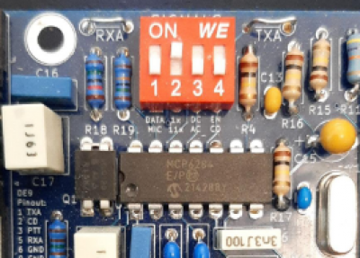
Starting with the SIGNALS switches near the top of the board when viewed with the “TARPN” logo at the bottom of the board.
This has a couple of important switches to set. When viewed like above DOWN is Off (0) and UP is On (1).
SWITCH 1. Sets the TX audio output level as a coarse setting. The DATA or On setting is a higher audio level and the MIC or Off setting is a lower audio level. The “DEV” potentiometer (left one marked “TX DEV” on the board) provides the fine control of the audio level. More on this below.
SWITCH 2. 1x or 11x is the RX audio level. The 11x setting is eleven times more receive audio than the 1x setting. Start with the 1x setting until you can tell if you have enough receive audio from your radio to the Nino TNC for decoding incoming signals. You may see the CRC LED (next to the TEST button) glow Red which indicates that the input audio from the radio to the Nino TNC is too high.
In general, for HF work set SWITCH 3 and SWITCH 4 to OFF (0 or Down).
Transmit Audio Test Procedures
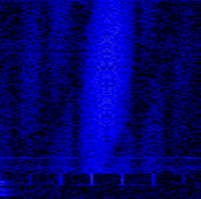
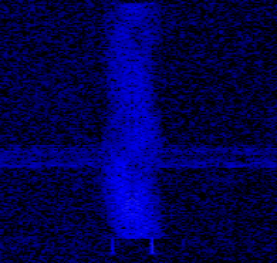
A helpful tool when making the TX audio adjustments is a web-accessible SDR which can hear your signal reliably. Nearly all of us can find one of these to use. This tool allows you to SEE the results of your adjustments and to ensure that your modulation level is set properly. If you see “wings” to the left and/or right of the main waveform envelope, the TX audio level is set to high and should be carefully reduced. Over-driving PSK waveforms in particular hurts your chances of being heard and decoded properly by the other station.
Set SIGNALS switches to 0100 which means:
SWITCH 1 to MIC (Off) and set SWITCH 2 to 1x (On). SWITCH 3 to AC (Off), SWITCH 4 to CD (Off)
Set the TX DEV potentiometer all the way to the left stop and then, turn it about half way to the right.
Connect the modem to the HF radio and tune to an empty channel and set the radio for a few watts of power for the time being (even better, use a dummy load!). Set the meter display on the HF radio to show you the ALC reading. Use the TEST button on the Nino TNC to make a short transmission and view the ALC meter on the HF radio. Note the ALC value and if it shows any reading at all, it is time to make the TX audio adjustment using the TX DEV potentiometer. You will likely need to turn this setting DOWN while transmitting in order to reduce the ALC to zero or near zero. If there is no ALC reading at this setting, slowly turn the potentiometer to the right while transmitting until it begins to rise. Your target is as close to zero ALC as you can get for all PSK waveforms (more on FSK waveforms later).
If you turn the potentiometer all the way to the right and still have no ALC while transmitting a TEST packet, then make a SIGNALS switch change to 1100 (on, on, off, off - left to right). This sets the TX audio coarse level to a higher value. Turn the TX DEV potentiometer all the way to the left (Off) and then to the right a 1/4 turn or so. Start the TEST packet process again and seek the ALC zero point.
Now attach the antenna feedline, turn up the HF radio's power level, and seek out a Web SDR which can hear you and admire your work as you transmit the TEST packet. If all looks good, then you are ready to use your HF system over the air at an appropriate power level for your license class and RF exposure limits.


