Table of Contents
Tait T2000 I & II series
The Tait T2000 I & II series are an older generation of “PMR” radios that have become popular with Amateurs due to their availability, reasonable pricing and models available for the 70cms, 2m and 4m bands (Note they're single band only).
A VHF T2010 has been tested at 1200b (AX.25), 2400b (IL2P) and 3600b (IL2P) performed well for both Tx and Rx. Deviation is limited in the hardware, so 9600b hasn't been tested yet. However, there is an untested conversion guide.
NOTE: The following T2010/15/20/30/35/40's have been tested up to 4800b GFSK_ILP2_CRC. UHF 70CM Series I and Series II 2M & 4M versions. All are 12.5KHz spec and work great. (G4WQG)
Note: Before rushing out to purchase one, read this entire page to understand the various models and be aware that several different options boards have surfaced which needed some reverse engineering before use - it might not be plug and play
The Series I radios have Light Grey decals and the Series II have Blue decals the front panel.. There are some “Auriga” branded radios available, but these are generally Series II.
220-01344-13 PCB Layout 220-01344-13_t2000_enhanced_hc11_platform.pdf
Models
| Model | Notes |
| 2010 | Tested working up to 4800b: 4 Channels |
| 2015 | Tested working up to 4800b: 24 channels and an LED screen |
| 2020 | Tested working up to 4800b: Multi channel with LCD Screen 100 or 1200 channels available |
| 2030 | Tested working up to 4800b: Trunked Version, but does have 4 conventional channels available |
| 2035 | Tested working up to 4800b: Trunked Version, but does have 4 conventional channels available |
| 2040 | Tested working up to 4800b: Trunked Version, but does have 10 conventional channels available |
Images
Images supplied by M6IMG
Front

Rear

Side, from left

Top view

Mic, and RJ12 connector

Power connector and pinout


Mounting Bracket

Disassembly
Due to the plethora of available options boards it's wise to partially disassemble the radio to examine the hardware prior to verify the pinout before attaching any external devices like TNCs.
Required Tools
You will need a:
- Torx T20 - for the screws on the base of the radio
- Torx T10 - for the internal screws that secure the logic and options board.
You might need a:
- 5mm socket, 3/16 socket, needle nose pliers, or small adjustable spanner - to remove the DBXX connector screwlocks
- Tait Release Key / Small flat blade screwdriver - to remove the mounting bracket
Removing the mounting bracket
Some of the radios will come with a mounting bracket. In theory these require a security key to remove the radio body from the bracket. In practise, some are loose and just slip out, with the brack sliding over the back of the radio.
If yours is more stubborn you will need to insert the security key or similarly shaped object into the hole in the left hand side of the control head near the volume control, which will release a tab and allow you to remove the radio body from the bracket.
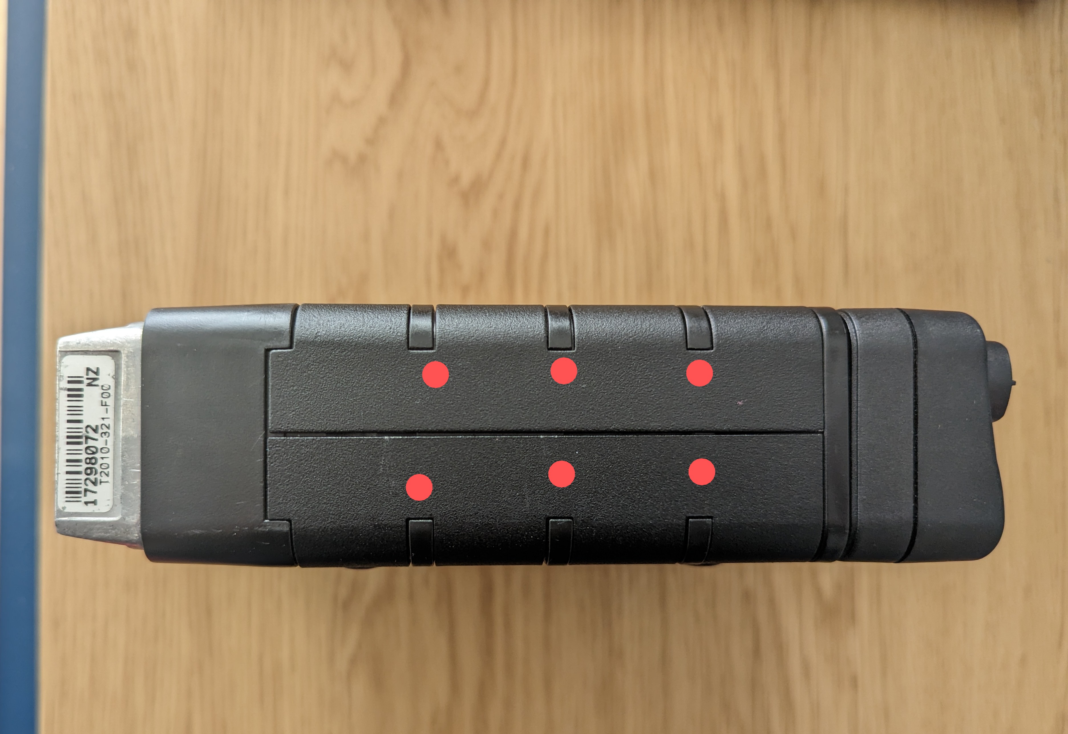
If you don't have a key or similar object, and don't mind some minor scratches to the bracket you can prise the two metal shells apart and remove them that way. Insert a thin flat blade screwdriver or similar implement in the gap between the two metal shells, and ease them over the plastic bumps (Marked with red dots in the image below) one at a time. Repeat for both sides, top and bottom.
Opening the radio
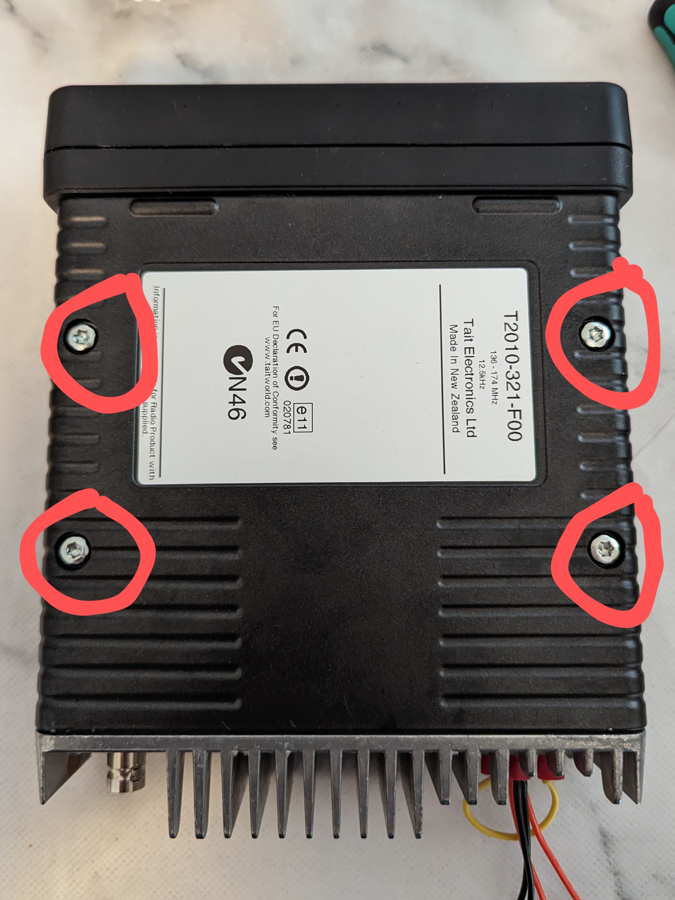
With the bracket removed you will see 4x T20 Torx screws on the bottom of the radio. Undo them, then flip the radio over and lift off the top shell.
Removing the Logic and Options boards
With the top shell removed, you'll be presented with the logic and options board if fitted.
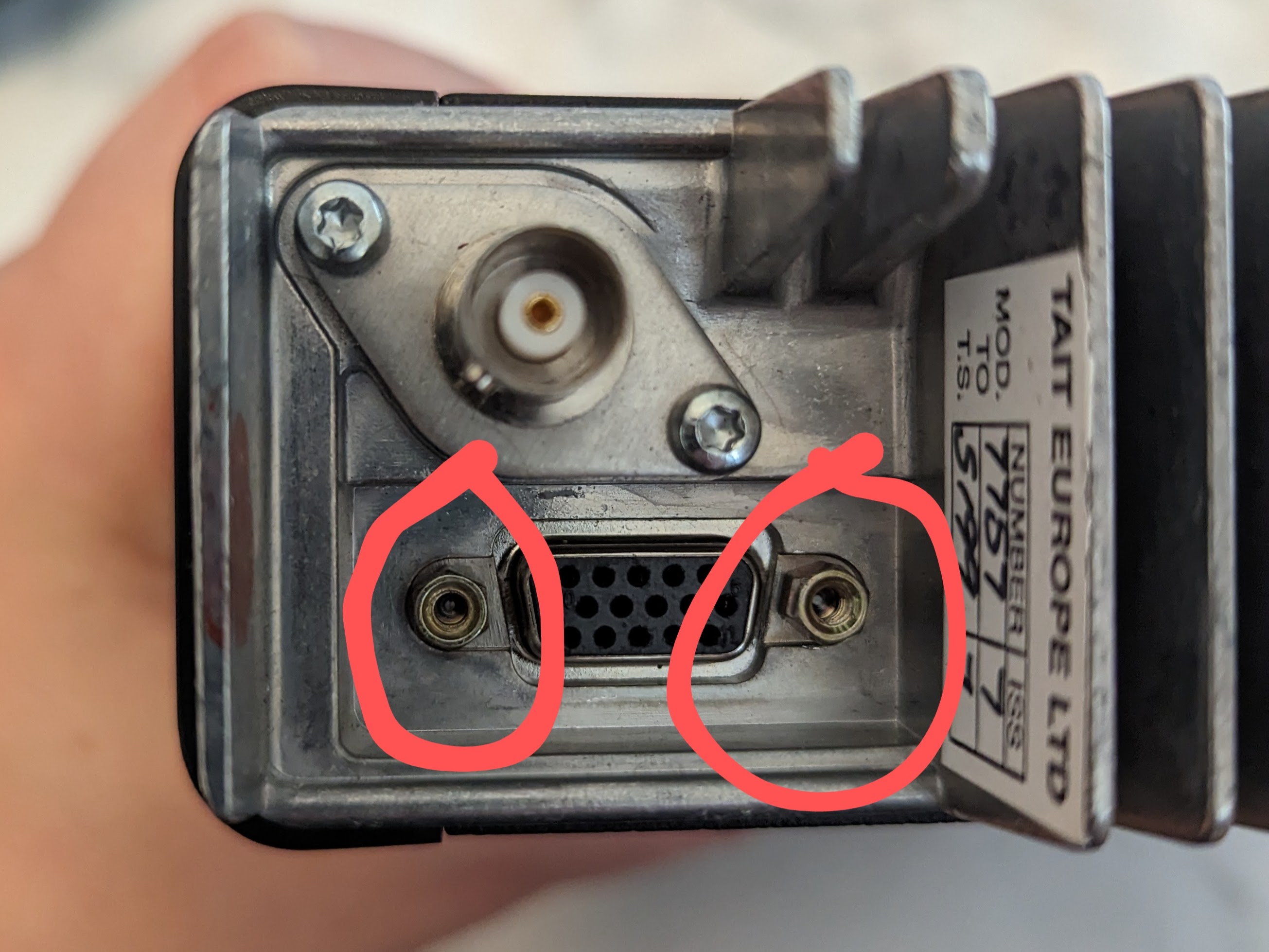
If the options board is fitted, first of all under the screwlock connectors either side of the DB9/DB15 connector on the back of the radio with an appropriate sized spanner / socket or needle nose pliers.
Then remove the ~6 T20 Torx Screws securing the PCB to the radio body:
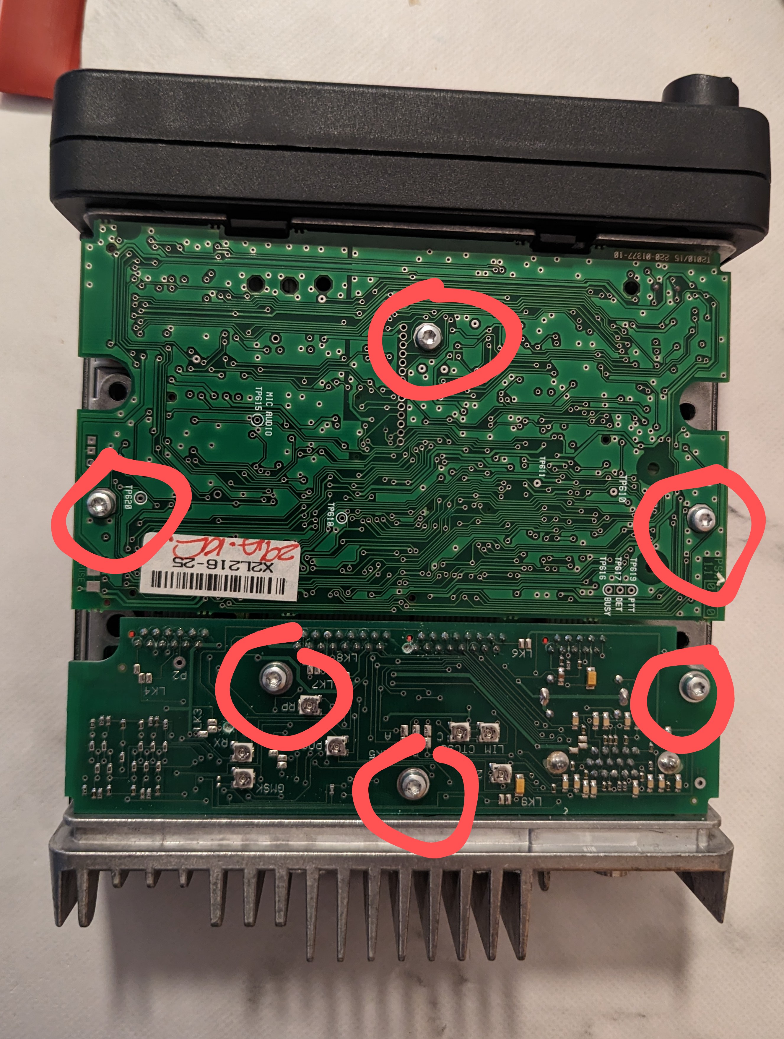
You should then be able to carefully remove the PCBs for inspection.
Reassembly
Reassembly is the opposite of disassembly
Options Boards
The T2000s expose options connections internally which made them popular for interfacing with data systems like those previously found in Taxis. It's not always possible to tell externally which board has been fitted, and various boards exist - some of which are undocumented.
TS02491
These were found in a pair of radios purchased at a radio rally. There was no indication on the outside of the radio these boards had been fitted, and it's functionality isn't 100% understood. The presence of the TCXO circuitry usually found on a separate module makes it difficult to modify, or swap out the options board without also adding a TCXO board. That said, the basic pin out required for most use cases has been discovered through trial and error.
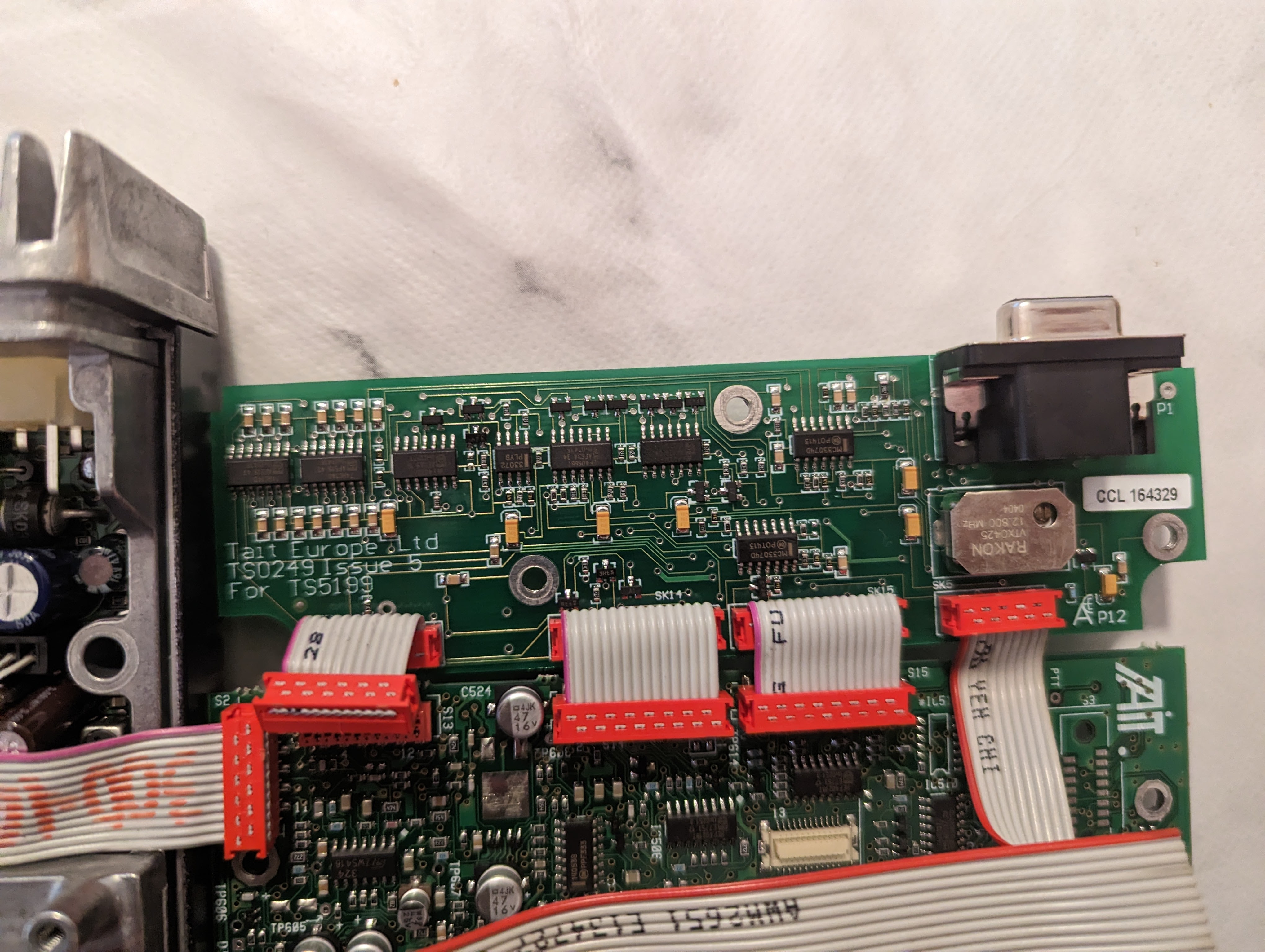
To program the radio you will need to open it up and either unplug S15 temporarily, or disconnect the PCB traces. I disconnected them by using a 1.5mm drill on the vias circled in red (Don't drill too deep, you just need enough to break the track):
Testing indicates the pin out is as follows (Use at your own risk). Note that other pins provide other functions including 13.8v, so make sure any cable you use isn't connecting undocumented pins to your TNC or similar:
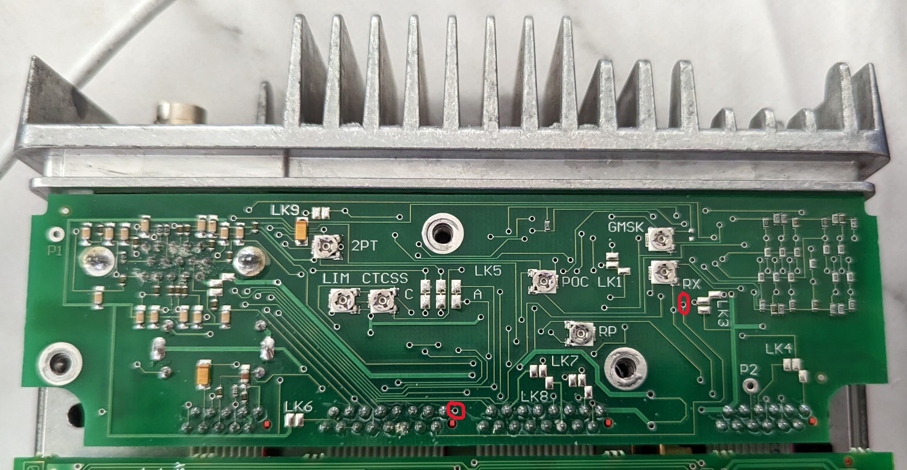
When Initially plugged into the NinoTNC the CRC led may be on or flickering.. To stop this turn the pot marked “RX” anticlockwise. To increase the TX deviation turn the pot clockwise marked “LIM”. Both of these are located on the option board.
| Pin | Usage | NinoTNC Pin |
| 7 | Ground | 6 |
| 10 | Rx Audio Out | 5 |
| 12 | Busy | N/A |
| 14 | TX Audio In | 1 |
| 15 | PTT | 3 |
Tait T2000-A81
A known-good, basic interfacing board which exposes Audio In, Audio Out, PTT and Ground on the accessory connector on the back of the radio.

Rear

| Pin | Usage | NinoTNC Pin |
| 2 | PTT (Active Low) | 3 |
| 3 | Tx Audio In | 1 |
| 4 | Gnd | 6 |
| 5 | Rx Audio Out | 5 |
| 7 | Busy / CoS | N/A |
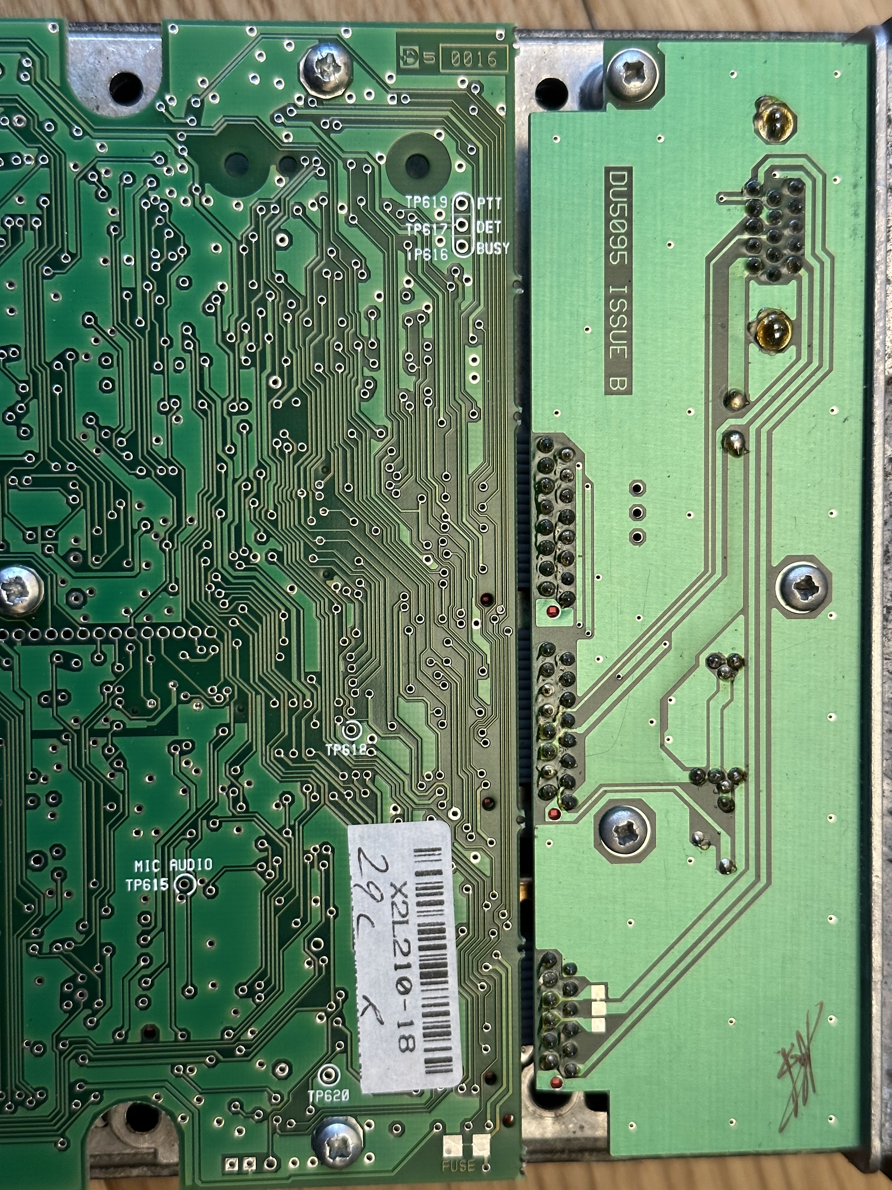
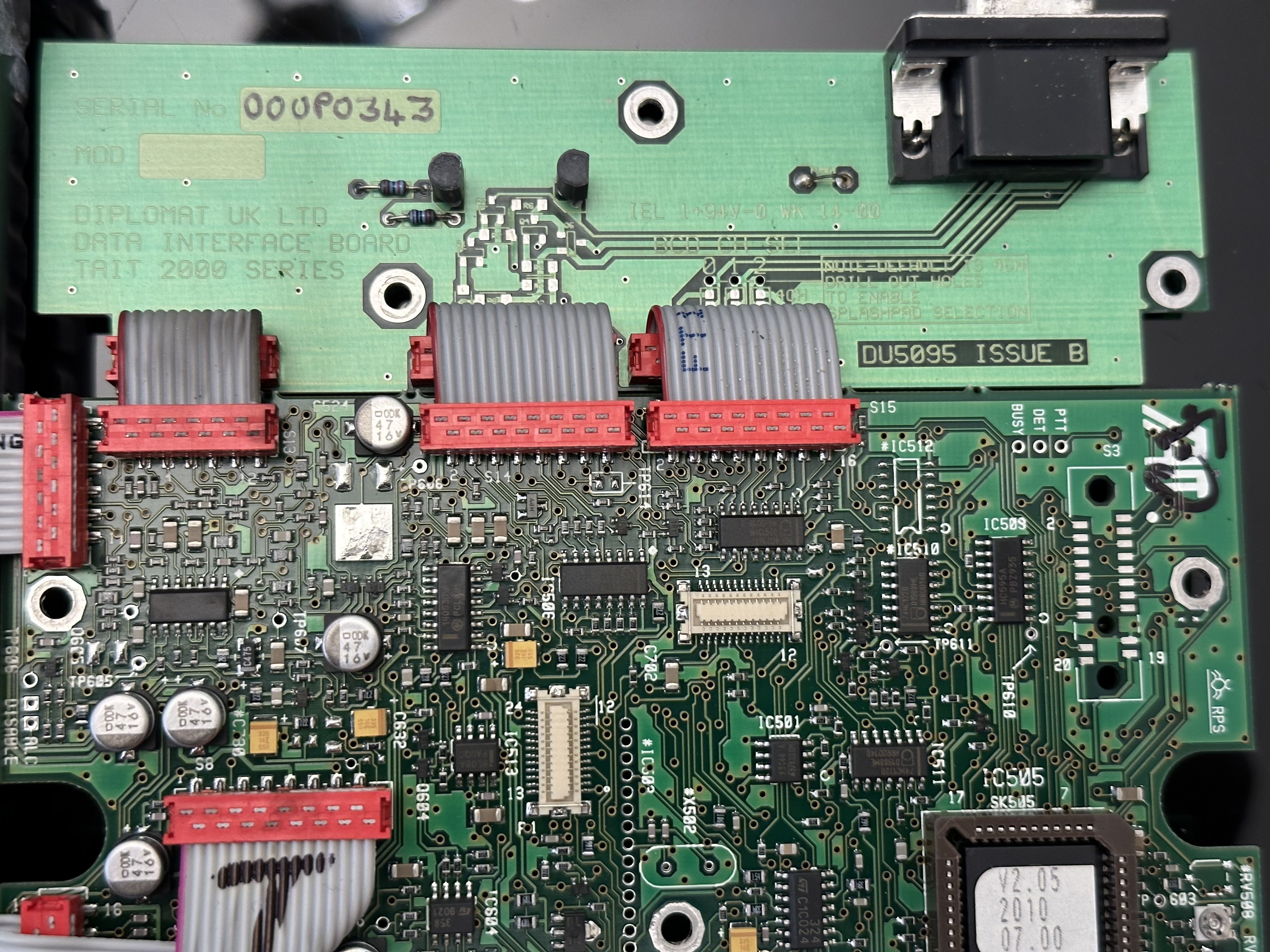
Diplomat UK Data Interface Board (DU5095)
A couple of T2010s from eBay turned up with this board fitted. It appears to be a slimmed down version of the T2000-A81 board, but the pinout remains the same.
| Pin | Usage | NinoTNC Pin |
| 2 | PTT (Active Low) | 3 |
| 3 | Tx Audio In | 1 |
| 4 | Gnd | 6 |
| 5 | Rx Audio Out | 5 |
| 7 | Busy / CoS | N/A |
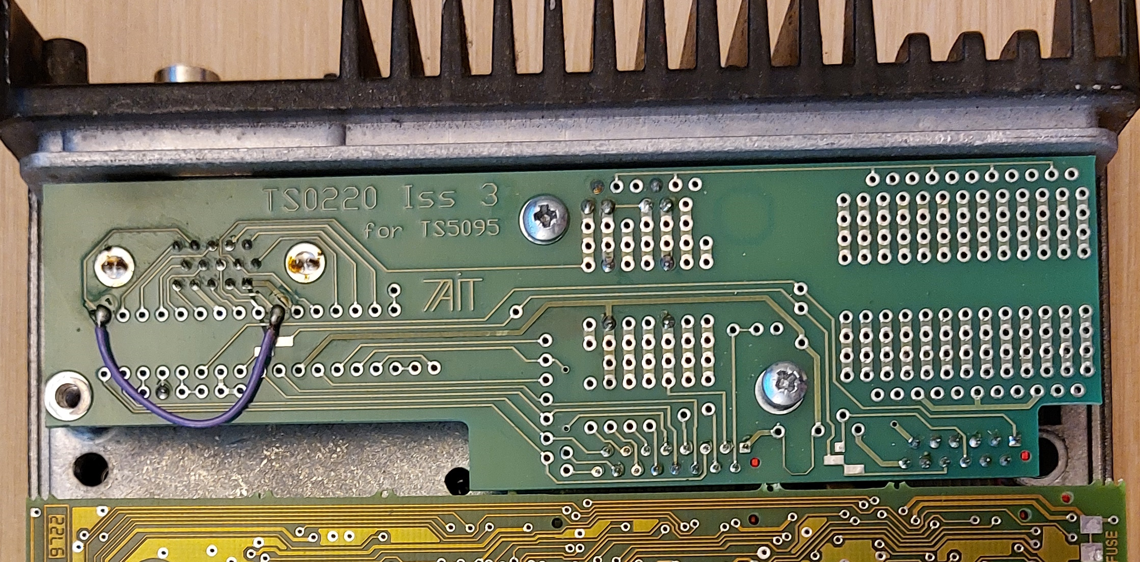
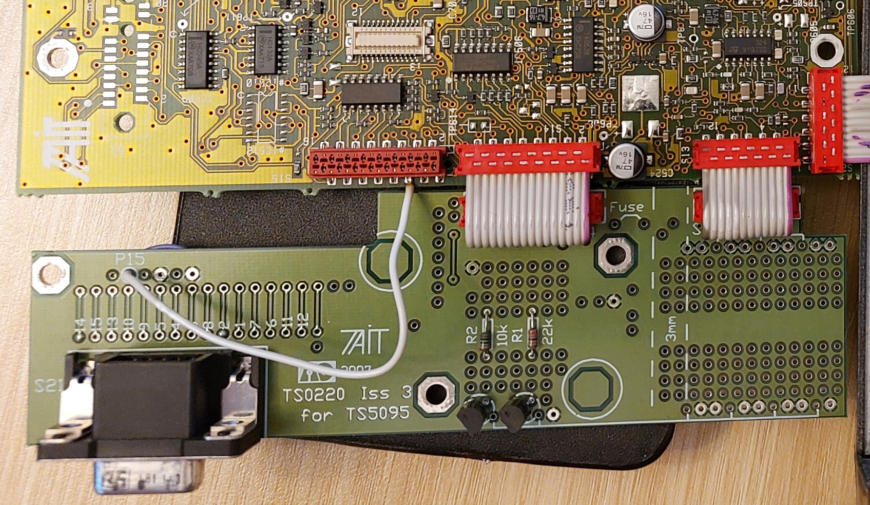
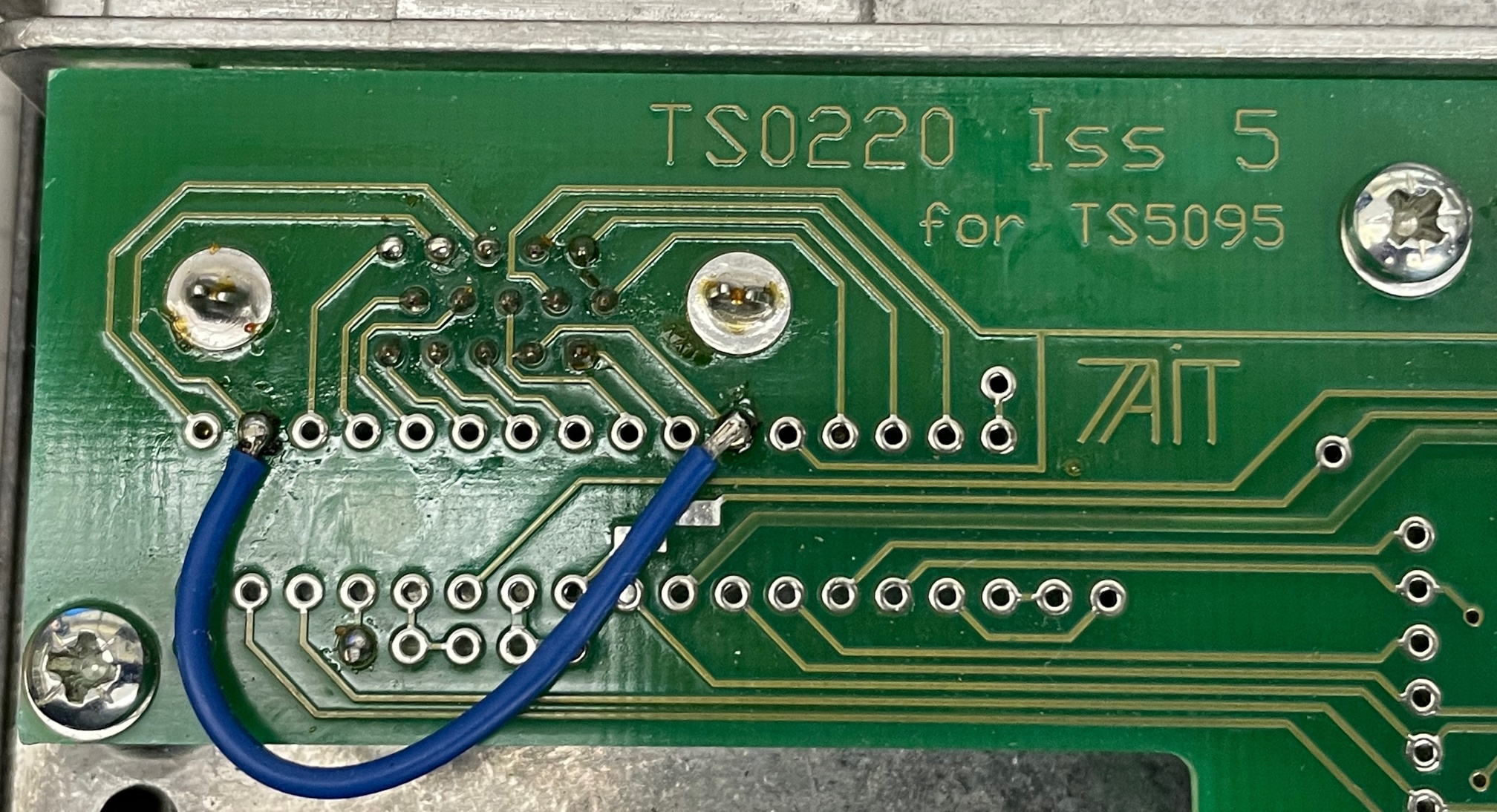
TS0220
A couple of different issue numbers of this board has been seen, that seem lartgely the same with some minor differences in PCB layout. Iss 3 has been confirmed with the pinout below, and Iss 5 is also believed to be the same based on https://gist.github.com/makuk66/8165a0971c99b613ea5524e2aec2e8a4. There are a couple of wires soldered on these examples so do check your version if you have it. Has been seen in a T2010-321-F00 and a T2010-321-F93.
With this board a NinoTNC Signals dip switch setting of 1100 was found to work (I'm not sure if the option board matters specifically for this setting).
| Pin | Usage | NinoTNC Pin |
| 2 | PTT | 3 |
| 3 | Tx Audio In | 1 |
| 5 | Rx Audio Out | 5 |
| 9 | Gnd | 6 |
Pin Outs
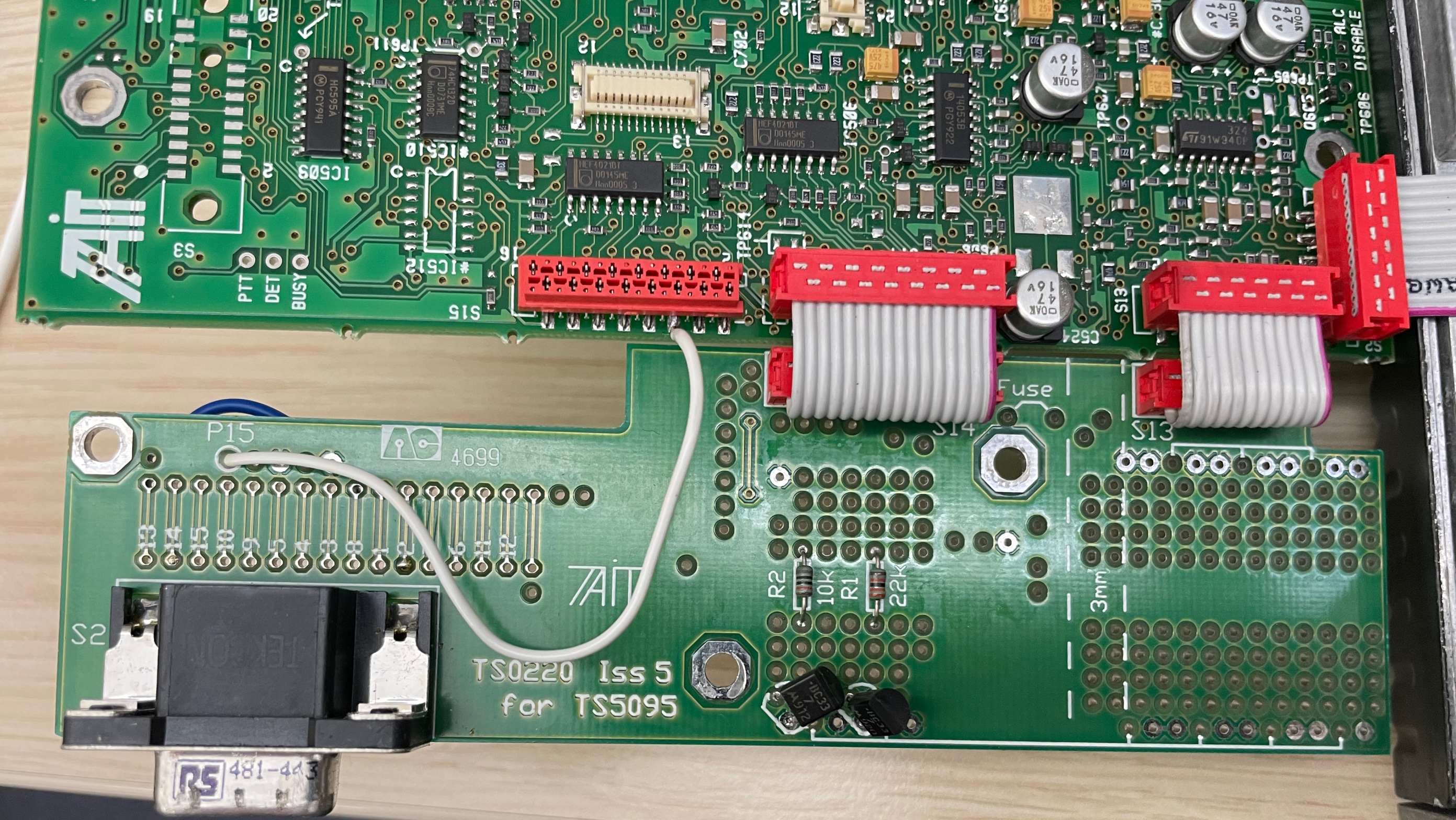
Should you find a Series II radio with no Option board fitted, you could fit a 9 pin D like this.. The pinout is Nino to Nino compatible.
(Note the green link from S14 Pin 5 to 6 is only fitted if the option board is removed and substituted to a 9 pin D.. Not always required depending on the logic board. If the radio stops transmitting when the option board is removed then add the link..)


__
Series I
Front Panel

This is the wiring for the Series I logic board to 9 Pin D, Nino to Nino compatable.

| Pin | Usage | NinoTNC Pin |
| S14 Pin 5 | PTT | 3 |
| S13 Pin 8 | Tx Audio In | 1 |
| S13 Pin 1 | Rx Audio Out | 5 |
| S13 Pin 11 | Gnd | 6 |
Power
The radios require 13.8v DC but will accept between 10.8V to 16v. Approximate current consumption is 300mA at idle, and up to 7A when transmitting on full power.
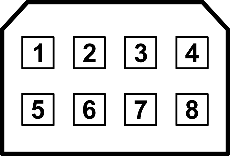
Pinout when looking at the rear of the radio, into the connector.
| Pin | Usage | Notes |
|---|---|---|
| 1 | Ignition Sense | Not normally connected |
| 2 | Not used | |
| 3 | DC in | |
| 4 | Speaker Ground | |
| 5 | External | Not normally connected |
| 6 | Internal Speaker Link | Bridge to pin 4 to enable internal speaker |
| 7 | GND | |
| 8 | External Speaker Output | To use external speaker, remove link between 4 and 7 and wire speaker between 8 and 4 |
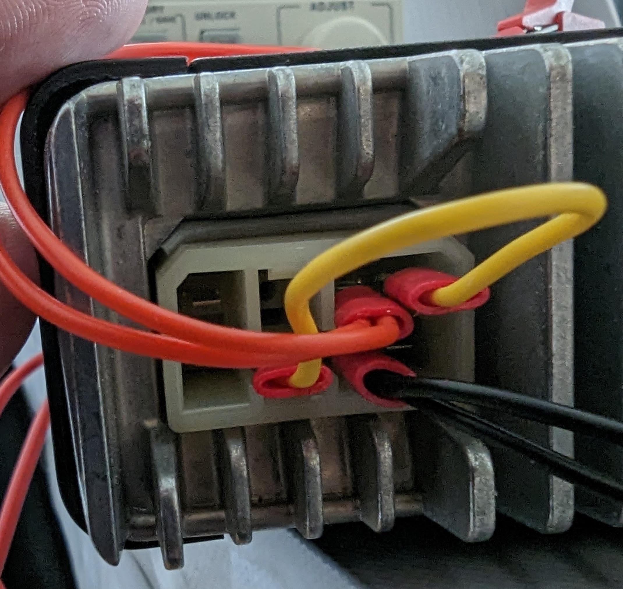
In a pinch, 2.8mm spade connectors fit firmly over the pins in the connector. There's a slight risk you might damage them, but if its a £5 radio from a rally you might not be too concerned. The spade connectors fit firmly and probably won't be pulled out by accident.
Front Mic
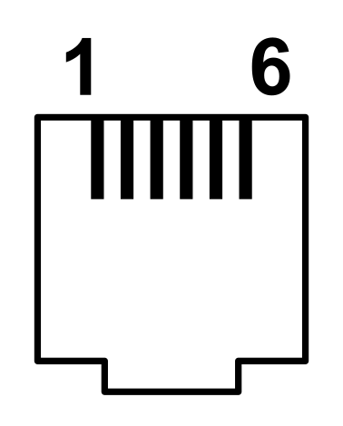
| Pin | Usage |
| 1 | 13.8v |
| 2 | Tx Data (Output) |
| 3 | Mic PTT |
| 4 | Mic Audio |
| 5 | Gnd |
| 6 | Rx Data (Input) |
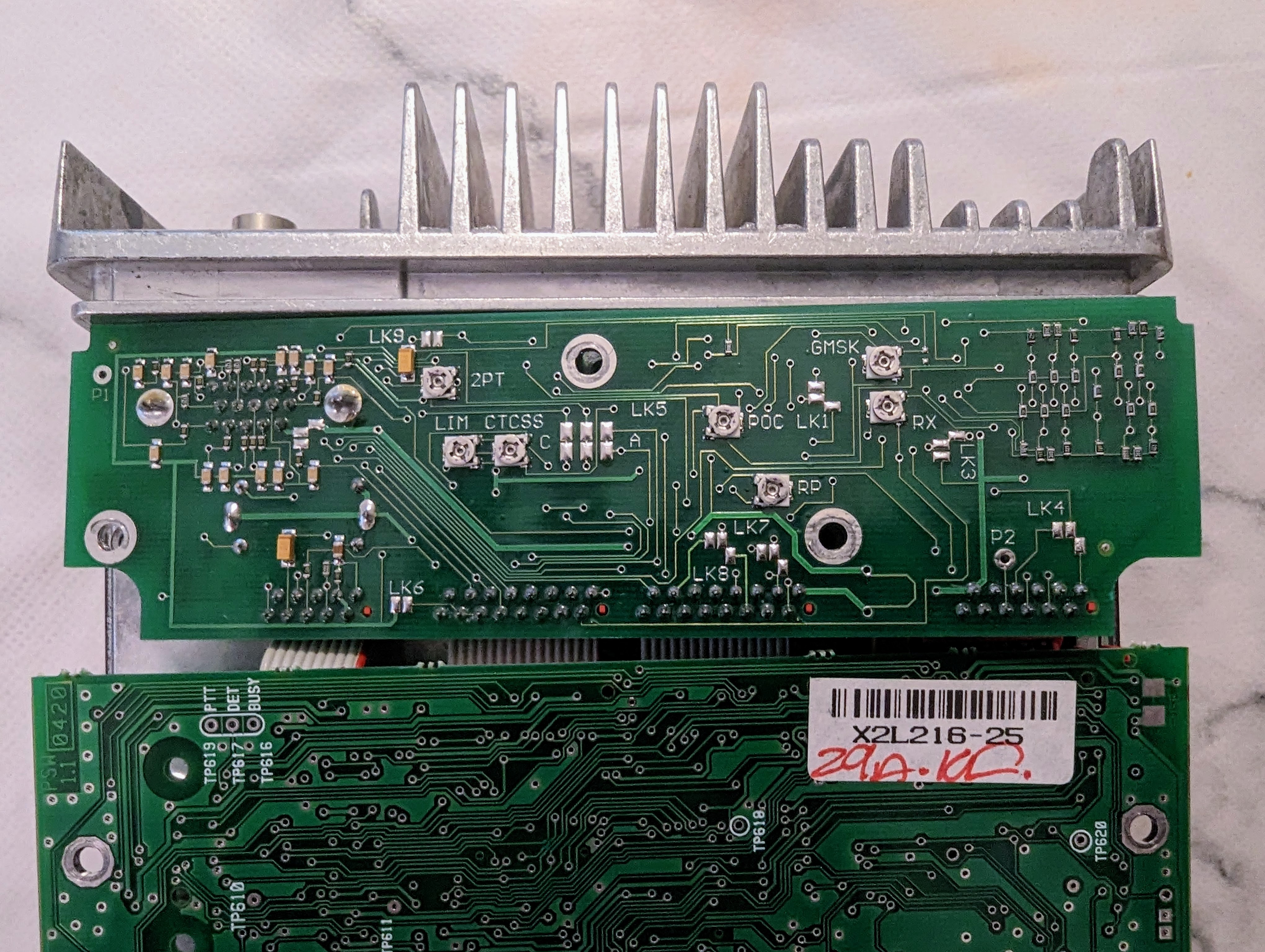
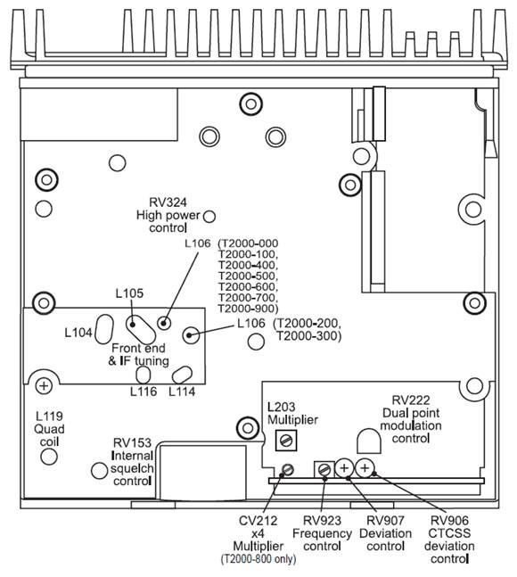
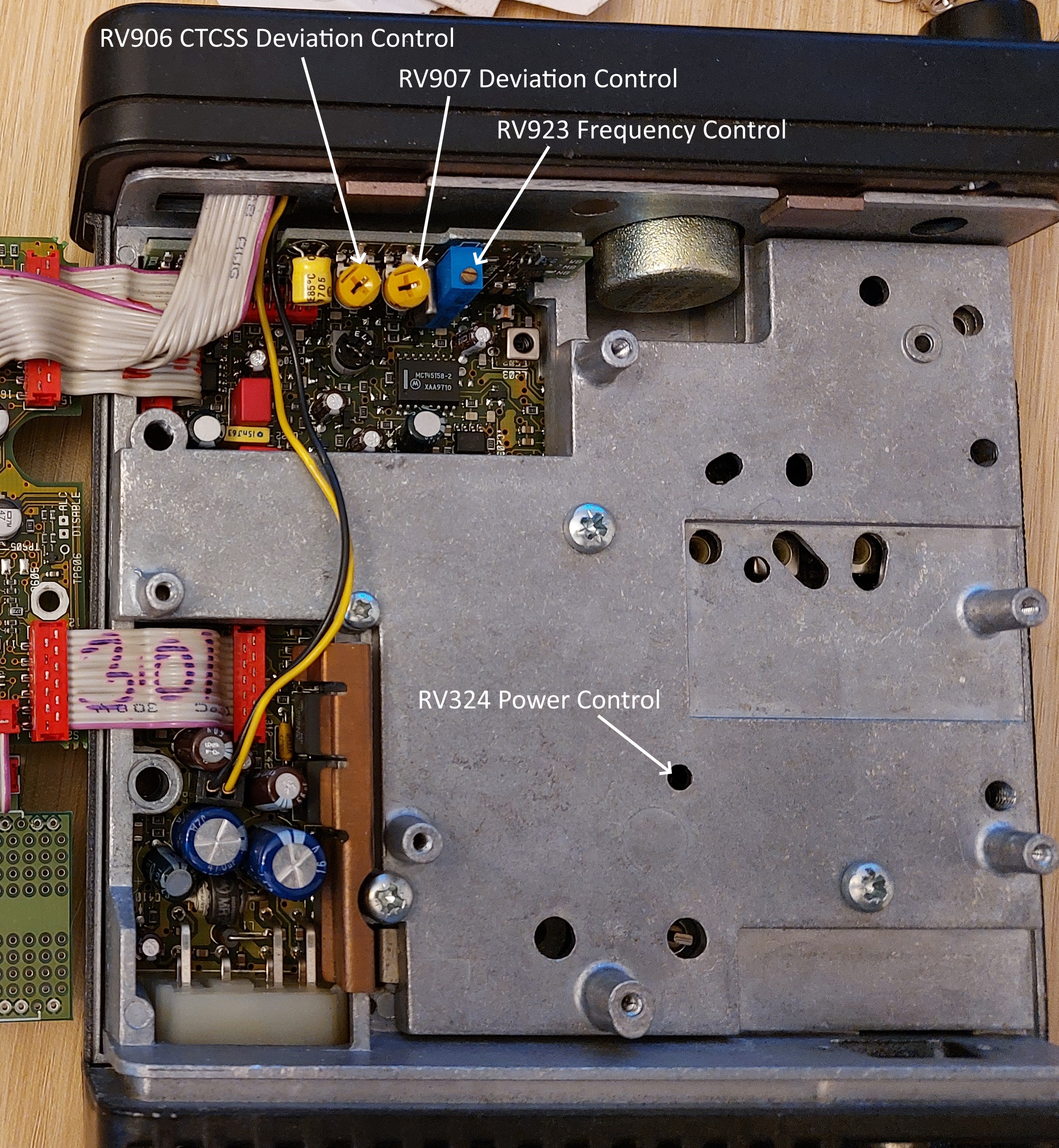
Internal Adjustment Controls
You may not need to mess with these, but you can use internal pots to fine-tune frequency, deviation, CTCSS deviation, and output power (and probably a few other things as well based on the diagram).
When programming the radio, you can set a channel to high or low power, and the power pot will affect both these settings. This can be useful if you are looking for a specific power output. There is a hole in the metal cover through which you can inset a flat head screwdriver to adjust. It is very sensitive, so only give it a little movement.
Programming
Programming the T2000II series is relatively straightforward. The software is referred to as the “T2000 Conventional Programming Application” and Version 3.00 is tested and working on Windows 11.
The programming for the T2000I series radio is a DOS program and requires to be run on a machine that runs Windows 7 or earlier with a serial port. I have not been able to run the DOS program using any DOS emulators and USB/serial adapters succesfully.
Hints
- The software only works with COM1-4 so you may have to re-assign your serial port in Windows Device Manager.
- The help menu in the Programming Application is very detailed. Worth looking at.
- If you've got a radio that's already programmed, it's best to start with a fresh configuration rather than reading from the radio and making changes, to avoid buried settings causing problems later down the line. The programming application will start with a fresh factory default config each time its opened.
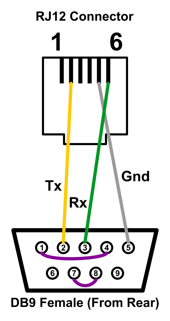
Programming Cable
You can use the diagram below to create a programming cable for the T2000 series. It assumes you're using a DB9 female connector to attach to the RS232 port on a computer or USB serial adapter. The programming operates at RS232 levels. I didn't need to include the purple link cables but they're included in the diagram just in case.
Packet Configuration
The following information should assist you with programming the radio for use with Packet. If a config section is omitted it doesn't need changing from the defaults.
Specifications
Select the band for the radio your programming. Note this must match the hardware.
Transmitter Setup
Set a suitable Transmit Timer and Lockout Duration to avoid the PTT getting stuck on for long periods.
![]()
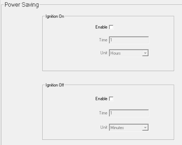
Power Saving
Disable the power saving functionality
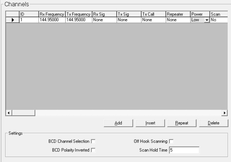
Channel Setup
Channels
The channels configuration is fairly intuitive