Table of Contents
Kenwood TK-90
An intriguing radio which looks great for unattended HF data use, since it is engineered for 100% duty cycle at 25W.
Has no data port on the back, but an accessory breakout cable can be added. Pinout is on p14 of the service manual, linked below.
Kenwood TK-90 ALE feature instructions
Requires programming. Both serial and USB-serial mic jack programming cable is available as a Kenwood part (see below) or off brand USB versions are also available. This implies it is just straight serial so a generic USB serial cable with an RJ45 plug crimped on the end may be suitable.
Has a “VFO mode” which implies it might not always have a “VFO mode” available.
Is ALE-capable, presumably with add-on.
Accessories
- KAT-1 - B51-8304-00 - Automatic antenna tuner
- KRK-5/6DH - B51-8445-20 - Remote kit
- KCT-31 - B51-8573-00 - PC interface cable
- VGS-1 - B51-8669-00 - Voice guide & storage unit
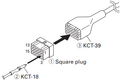
- KCT-39 - Accessory breakout cable (stocked by radioswap)
- KPG-102D - Programming Disc (CD)
- KPG-46 / KPG-46A - Serial programming cable
- KPG-46U - USB programming cable
- KCT-18 - Ignition sense cable
- KES-3 - External speaker
- KIF-2 - 2.7kHz SSB filter
- YF-107C - 500Hz CW Filter for TS-480HX/SAT
- KLF-2 - Line noise filter
- KMB-10 - Key lock adapter
- KMB-9 - Mounting bracket
- KMC-30 - Standard hand microphone
- KMC-32 - Hand microphone with keypad
- KMC-35 - Slim-line hand microphone
- KMC-36 - Slim-line hand microphone with keypad
- KPE-2 - ALE unit
- KRK-5 - Panel Separation Kit (Requires KCT-22M, 22M2 or 22M3)
- PG-20 - DC cable (7m)
- VGS-1 - Voice guide/Storage unit
For best results it has been recommended to use a KMC-32 keypad microphone for ease of use with the menus.
Data modes / modem use
Install KCT-39 - accessory breakout cable.
Build a cable (the plug parts come with KCT-39):
- RX Audio → pin 4 - DEO - brown
- TX Audio → pin 5 - DI - orange
- PTT → pin 6 - DPTT - yellow
- Ground → pin 8 - GND - blue
NB - DI is “data input audio”, DEO is “data output audio”.
KCT-39 pinout
| Pin | Colour | Internal | Name | Notes |
|---|---|---|---|---|
| 1 | Red | CN9-1 | KEY | |
| 2 | Pink | CN10-1 | IGN | |
| 3 | Black | CN9-3 | GND | Ground |
| 4 | Brown | CN10-3 | DEO | RX audio |
| 5 | Orange | CN10-2 | DI | TX audio |
| 6 | Yellow | CN9-8 | DPTT | PTT |
| 7 | Green | CN9-7 | RTK | |
| 8 | Blue | CN9-9 | GND | Ground |
| 9 | Purple | CN9-12 | AUX3 | |
| 10 | Gray | CN9-10 | AUX1 | |
| 11 | White | CN9-11 | AUX2 | |
| 12 | NC | NC | - | |
| 13 | NC | NC | - | |
| 14 | Sky blue | CN9-6 | RXD1 | Assumed to be serial, maybe TS-2000-alike |
| 15 | Turquoise | CN9-5 | TXD1 | Assumed to be serial, maybe TS-2000-alike |
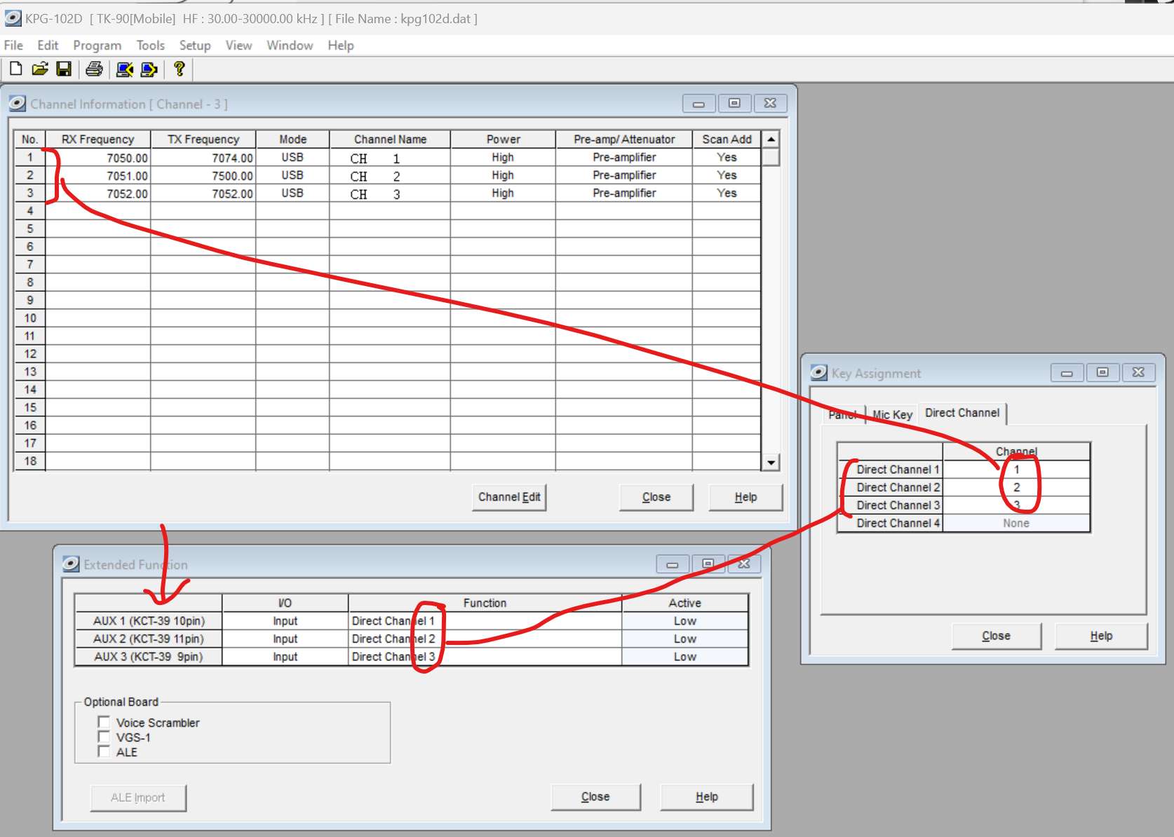
External channel control looks feasible:
Dealer mode
Boot radio into dealer mode by holding down B while powering up. Scroll down to FUNCTION, and press D. Adjust settings as desired. Press the red button twice to exit and reboot.
Some recommended settings in DEALER mode:
- M2 MIN VOLUME: 0 - means the radio can boot with the volume turned to zero
- M12 TOT: TX time out timer. Set to, say, 3 minutes
- M13 VFO TX PWR: self explanatory
- M19 DI LEVEL: data input audio level, set as required
- M20 DEO LEVEL: data output audio level, set as required
- M22 DATA S-BAND: which sideband will data be transmitted on - generally set to USB
Adjusting TX audio response
Remove the top lid of the radio- 8 screws.
Trimmer VR852 is TX sensitivity - max sensitivity to TX audio input is fully clockwise.
To set up TX audio, I recommend the following procedure:
- in the dealer menu, set DI to 4, the default
- set the radio to 100W
- set your modem to its maximum volume level (on NinoTNC I recommend DIP switch 1 is down/off (i.e. lower transmit audio range and with its DEV pot set to maximum)
- have the modem transmit repeated frames (on NinoTNC, hold test TX button for ~20 seconds and release)
- turn VR852 until a power meter connected to the radio reads say 50W
- adjust the modem output volume down until the power meter reads the desired output power, e.g. 25W
Navigating
The A-D buttons are programmable, but the functions they have shipped to us with are as follows.
Pressing A in VFO mode gets you a blinking cursor. Move the cursor left/right with <C and D> buttons. Change that digit with CH up and CH down. Exit with the red button.
Pressing B cycles between preamp / attenuator settings.
Pressing C gets you the clarifier settings.
Pressing D cycles between modes (i.e. USB, LSB, DATA, CW, AM, FSK)
Pressing square gets you a basic menu.
Booting the radio with B held gets you a DEALER menu. This is pretty safe. More in here than the basic menu.
Booting the radio with A held gets you an ADJUSTMENT menu. Warning: this is a service menu, for radio alignment, and you can break things very easily in here, requiring realignment which requires lab tools and knowledge.
There is supposed to be a TEST mode when booting the radio with D held, but this does not appear to be enabled.
All of the above is in the service manual.
Mic pinout
Pin 8 is towards the bottom of the radio.
- DM
- MIC
- PTT - common with a point labelled PTT/TXD
- SB
- HK - connected to a pin labelled RXD0 and to +5V via a 4.7k resistor
- ME
- GND
- BLC
Abbreviations are from the schematics in the service manual, meanings as yet unknown.
A known working cable has wiring:
- White - Pin 2 (MIC)
- Red - Pin 5 (SB)
- Black - Pin 6 (HK)
The cable has a PL2303 USB serial chip.


